目录索引

译文
根据Unity官方文档(ShaderLab 命令:模板 – Unity 手册)所描述的:
模板缓冲区为帧缓冲区中的每个像素存储一个 8 位整数值。为给定像素执行片元着色器之前,GPU 可以将模板缓冲区中的当前值与给定参考值进行比较。这称为模板测试。如果模板测试通过,则 GPU 会执行深度测试。如果模板测试失败,则 GPU 会跳过对该像素的其余处理。这意味着可以使用模板缓冲区作为遮罩来告知 GPU 要绘制的像素以及要丢弃的像素。
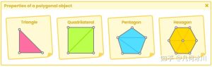
要想理解这段话的意思,我们需要先了解到模板缓冲(Stencil Buffer)本身就是一个必须创建的“纹理”。为此,它会为帧缓冲中的每个像素存储一个 0 至 255 的整数值。
![图片[1]-《Unity着色器圣经》3.2.4 | ShaderLab模板-软件开发学习笔记](https://gamedevfan.cn/wp-content/uploads/2025/05/image-42-1024x442.jpeg)
我们已经知道的是,当我们在场景中摆放模型时,其信息(例如顶点位置)会被发送到顶点着色器。在这个阶段,模型经历了从模型空间到世界空间、观察空间、裁剪空间的变换。当然,这一阶段只针对于那些位于位于相机视锥体内的模型。
当模型信息被正确处理后,处理过的信息就被发送到光栅化阶段,将模型投影到屏幕坐标系的一系列具体像素上。然而在显示到屏幕上之前,像素还需要经过剔除和深度测试阶段。在这一阶段,我们可以在着色器中操作各种进程,其中包括剔除、深度写入、深度测试和模板。
模板缓冲干的基本功能是开启模板测试(Stencil Test),该测试允许丢弃还未经过片元着色器处理的“片元”(像素)们,在着色器中产生蒙版效果。执行 模板测试 的语法如下:
if ( StencilRef & StencilReadMask [Comp] StencilBufferValue &
StencilReadMask)
{
    Accept Pixel.
}
else
{
    Discard Pixel.
}“模板参考值(StencilRef)”是我们要传入模板缓冲的参考值。这是什么意思呢?还记得我们之前提到过模板缓冲是一种覆盖了模型像素的区域“纹理”吗?模板参考值就像一个 ID,映射了 模板缓冲 中的所有像素。
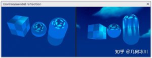
比如说,我们打算把模板参考值设为2:
![图片[2]-《Unity着色器圣经》3.2.4 | ShaderLab模板-软件开发学习笔记](https://gamedevfan.cn/wp-content/uploads/2025/05/image-41-1024x363.jpeg)
在上图的例子中,所有覆盖胶囊体的像素区域都已经标记成了模板参考值的值,所以现在模板缓冲等于2。
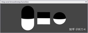
随后,会为所有具有模板参考值(默认值为 255)的像素创建一个遮罩(StencilReadMask)。
![图片[3]-《Unity着色器圣经》3.2.4 | ShaderLab模板-软件开发学习笔记](https://gamedevfan.cn/wp-content/uploads/2025/05/image-40-1024x362.jpeg)
因此,上述操作如下所示:
if ( 2 & 255 [Comp] 2 & 255)
{
    Accept Pixel.
}
else
{
    Discard Pixel.
}代码中的“Comp”代表返回真(true)或假(false)的比较函数。如果返回真,则程序将会把该像素写入帧缓冲中,反之舍弃该像素。
有以下几种预设的比较函数:
- Comp Never: 该操作将始终输出假(false)。
- Comp Less: <. 小于
- Comp Equal: ==. 等于
- Comp LEqual: ≤. 小于等于
- Comp Greater: >. 大于
- Comp NotEqual: !=. 不等于
- Comp GEqual: ≥. 大于等于
- Comp Always: 该操作将始终输出真(true)。
我们至少需要两个着色器来使用模板缓冲:一个用于遮罩,一个用于被遮罩的对象。
现在假设场景中有三个物体:一个立方体、一个球体和一个正方形。球体被放置在立方体里面,我们打算把正方形当作隐藏正方体显示球体的“遮罩”。要想实现这个效果,让我们创建一个名为 USB_stencil_ref 的着色器吧,相关语法如下所示:
SubShader
{
    Tags { "Queue"="Geometry-1" }
    ZWrite Off
    ColorMask 0
    Stencil
    {
        Ref 2 // 模板参考值
        Comp Always
        Pass Replace
    }
}
![图片[4]-《Unity着色器圣经》3.2.4 | ShaderLab模板-软件开发学习笔记](https://gamedevfan.cn/wp-content/uploads/2025/05/image-39-1024x360.jpeg)
让我们来分析一下上面的代码,这个着色器是给正方形使用的。我们做的第一件事是将正方形的“队列(Queue)”设置成了“Geometry – 1”。我们已经学习过,在渲染队列中 Geometry 的默认值为 2000,因此“Geometry – 1”就等于 1999, Z 缓冲将先处理正方形(遮罩)。不过 Unity 默认根据物体在场景中与相机的深度关系来处理物体,因此我们必须设置属性“ZWrite Off”来禁用深度写入。
接着,“ColorMask 0”将颜色遮罩设置成0,这样遮罩的像素就会被帧缓冲舍弃,变成透明的。
这时候我们的正方形还没有达到预期的效果。因此,我们接下来要做的就是添加“模板(Stencil)”命令,使其发挥这样的功能。
“Ref 2”是我们的模板参考值,它在 GPU 里与当前模板缓冲内的值根据设置的“比较函数”进行比较。
“Comp Always”确保了模板缓冲中正方形所覆盖的区域被设置为 2 。最后,“Pass Replace”指定用模板参考值“替换”模板缓冲区的当前值。
现在我们来分析被遮罩的物体(立方体)。我们需要创建另一个名为 USB_stencil_value 的着色器,相关语法如下所示:
SubShader
{
    Tags { "Queue"="Geometry" }
    Stencil
    {
        Ref 2
        Comp NotEqual
        Pass Keep
    }
    …
}![图片[5]-《Unity着色器圣经》3.2.4 | ShaderLab模板-软件开发学习笔记](https://gamedevfan.cn/wp-content/uploads/2025/05/image-38-1024x364.jpeg)
和我们先前写的着色器不同的是,我们并没有关闭深度写入,这样立方体就会按根据它和相机之间的深度关系被渲染。随后我们添加了模板命令,这样立方体就会被遮罩了。我们再次添加“Ref 2”,将该着色器与 USB_stencil_ref 关联起来,以获得遮罩。
接着我们使用了“Comp NotEqual”比较函数。这说明立方体周围不被正方形遮挡的区域将被渲染,因为模版测试通过(无比较或为真)。
另一方面,在立方体被正方形遮挡的部分,由于二者的模板参考值相等,因此模板测试不会通过,像素将被舍弃。“Pass Keep”表示立方体保留模板缓冲区的当前内容。
如果我们想要使用多个遮罩,我们可以指定不同于“2”的其他模板参考值。
原文对照
According to the official documentation in Unity:
The Stencil Buffer stores an integer value of eight bits (0 to 255) for each pixel in the Frame Buffer. Before running the fragment shader stage for a given pixel, the GPU can compare the current value in the Stencil Buffer with a determined reference value. This process is called Stencil Test. If the Stencil Test passes, the GPU performs the depth test. If the Stencil Test fails, the GPU skips the rest of the processing for that pixel. This means that you can use the Stencil Buffer as a mask to tell the GPU which pixels to draw and which pixels to discard.
To understand the above description, we must take into consideration that the Stencil Buffer itself is a “texture” that must be created. For this, it stores an integer value from 0 to 255 for each pixel in the Frame Buffer.
As we already know, when we position objects in our scene, their information is sent to the vertex shader stage (e.g. vertex position). Within this stage, the attributes of our object are transformed from object-space to world-space, then view-space, and finally clip-space. This process occurs only for those objects that are inside the frustum of the camera.
When this information has been processed correctly, it is sent to the rasterizer which allows us to project in pixels the coordinates of our objects in the scene, however, before reaching this point it goes through a previous stage of processing called Culling and Depth testing. In this stage various processes occur that we can manipulate within our shader, among them are Cull, ZWrite, ZTest and Stencil.
Basically what the Stencil Buffer does is activate the Stencil Test, which allows the discarding of “fragments” (pixels) so that they are not processed in the fragment shader stage, thus generating a mask effect in our shader. The function performed by the Stencil Test has the following syntax:
if ( StencilRef & StencilReadMask [Comp] StencilBufferValue &
StencilReadMask)
{
    Accept Pixel.
}
else
{
    Discard Pixel.
}“StencilRef” is the value that we are going to pass to the Stencil Buffer as a reference, what does this mean? Remember that the Stencil Buffer is a “texture” that covers the area in the object’s pixels. The StencilRef works as an id that maps all the pixels found in the Stencil Buffer.
For example, we are going to make the StencilRef value 2.
In the example above, all the pixels covering the capsule area have been marked with the value of the StencilRef, therefore now the Stencil Buffer equals 2.
Subsequently, a mask (StencilReadMask) is created for all those pixels that have a reference value that by default has the value 255.
Thus, the above operation is as follows.
if ( 2 & 255 [Comp] 2 & 255)
{
    Accept Pixel.
}
else
{
    Discard Pixel.
}“Comp” refers to a comparison function that gives a true or false value. If the value is true, the program writes the pixel in the Frame Buffer, otherwise, the pixel is discarded.
Within the comparison functions, we can find the following predefined operators:
- Comp Never: The operation will always deliver false.
- Comp Less: <.
- Comp Equal: ==.
- Comp LEqual: ≤.
- Comp Greater: >.
- Comp NotEqual: !=.
- Comp GEqual: ≥.
- Comp Always: The operation will always deliver true.
We need at least two shaders to use the Stencil Buffer: One for the mask and one for the masked object.
Let’s suppose we have three objects in our scene: A Cube, a Sphere and a square. The Sphere is inside the Cube, and we want to use the square as a “mask” to hide the Cube so that the Sphere inside can be seen. To create this example mask, we will create a shader called USB_stencil_ref and its syntax would be the following:
SubShader
{
    Tags { "Queue"="Geometry-1" }
    ZWrite Off
    ColorMask 0
    Stencil
    {
        Ref 2 // StencilRef
        Comp Always
        Pass Replace
    }
}Let’s analyze the above. The first thing we did was configure “Queue” equals “Geometry minus one”. Geometry defaults to 2000, therefore, Geometry minus 1 equals 1999, this will process our square (mask), to which we will apply this shader, first in the Z-Buffer. However, as we know, Unity by default processes objects according to their position in the scene concerning the camera, therefore if we want to disable this function we must set the property “ZWrite to Off“.
Then we set “ColorMask to zero” so that the mask pixels are discarded in the Frame Buffer and appear transparent.
At this point, our square still does not work as a mask, therefore what we must do next is add the command “Stencil” so that it functions as such.
“Ref 2” (StencilRef), our reference value, is compared on the GPU with the current content of the Stencil Buffer using the operation defined in the “comparison operation”.
“Comp Always” makes sure to set a “2” in the Stencil Buffer, taking into account the area covered by the square on the screen. Finally, “Pass Replace” specifies that the current values of the Stencil Buffer be “replaced” by the StencilRef values.
Now we are going to analyze the object that we want to mask. We will create another shader called USB_stencil_value to illustrate this. Its syntax is as follows:
SubShader
{
    Tags { "Queue"="Geometry" }
    Stencil
    {
        Ref 2
        Comp NotEqual
        Pass Keep
    }
    …
}Unlike our previous shader, we will keep the Z-Buffer active so that it is rendered on the GPU according to its position relative to the camera. Then we add the Stencil command so that our object can be masked. We add “Ref 2” again to link this shader with USB_stencil_ref for the mask.
Then, in the comparison operation, we assign “Comp NotEqual”. This states that the Cube area exposed around the square will be rendered because the Stencil Test passes (no comparison or true).
On the other hand, for the square area, being equal (Equal) the Stencil Test will not pass, and the pixels will be discarded. “Pass Keep” means that the Cube maintains the current content of the Stencil Buffer.
If we want to work with more than one mask, we can give a Ref property number different to “2”.
![[udemy]在 Unity 中创建 RPG 游戏的终极指南-软件开发学习笔记](https://gamedevfan.cn/wp-content/uploads/2025/04/TheUltimateGuidetoCreatinganRPGGameinUnity.webp)
![[udemy]学习在 Unity 和 C# 中创建吸血鬼幸存者风格的游戏-软件开发学习笔记](https://gamedevfan.cn/wp-content/uploads/2025/04/LearnToCreateAVampireSurvivorsStyleGameinUnityC.webp)
![[udemy] 在 Godot 4 中创建完整的 2D 幸存者风格游戏-软件开发学习笔记](https://gamedevfan.cn/wp-content/uploads/2025/05/CreateaComplete2DSurvivorsStyleGameinGodot4.webp)
![[gamedev tv] RPG核心战斗力的创造者 :学习中级 Unity C# 编码-软件开发学习笔记](https://gamedevfan.cn/wp-content/uploads/2025/04/RPGCoreCombatCreatorLearnIntermediateUnityCCoding.png)
![[gamedev tv] 完成 Godot 3D:使用 Godot 4 开发您自己的 3D 游戏-软件开发学习笔记](https://gamedevfan.cn/wp-content/uploads/2025/05/CompleteGodot3DDevelopYourOwn3DGamesUsingGodot4.webp)


暂无评论内容