目录索引

译文
我们在着色器中常常使用一种叫“结构体(struct)”的数据类型。对有使用过C语言的人来说,结构体是一种复合数据类型,它定义了由相同类型的多个元素组成的分组列表,并允许通过单个指针访问不同的变量。我们将在着色器中使用结构体来定义输入和输出,其语法如下所示:
struct name
{
    vector[n] name : SEMANTIC[n];
};首先,我们声明结构体,然后声明其名称,接着将向量语义存储在结构体字段中,以便后续使用。“name”对应的是结构体的名称,“vector”对应的是我们将在后续使用到的向量类型(如 float2、half4等),用于指定语义。最后,”SEMANTIC(语义)”对应的是我们将作为输入或输出传递的语义。
在我们新建着色器时,Unity 会自动添加两个结构函数,分别是 appdata 和 v2f。appdata(application data) 对应“顶点输入”,而 v2f(vertex to fragment) 则指“顶点输出”。
顶点输入 将是我们存储模型属性(如顶点位置、法线等信息)的地方,作为将这些信息传入“顶点着色器”的“入口”。而顶点输出则是我们存储光栅化属性的地方,以便将这些信息传入后续的“片元着色器”。
我们可以将语义视为对象的 “访问属性”。根据微软官方文档(语义 – Win32 apps):
语义是附加到着色器输入或输出的字符串,用于传达有关参数的预期用途的信息。 在着色器阶段之间传递的所有变量都需要语义。
让我们通过 POSITION[n] 语义来介绍这个概念。
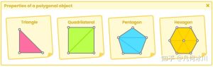
在本书的开头部分(1.0.1 | 多边形物体的属性),我们已经知道了一个物体的顶点中包含了顶点位置、切线、法线、UV 坐标和颜色的信息。语义允许程序单独访问这些属性,也就是说,如果我们声明一个四维向量,并将 POSITION[n] 语义传递给它,那么该向量将包含模型顶点的位置信息。假设我们声明了以下向量:
float4 pos : POSITION;代码声明了一个名为“pos”的四维向量,它储存了模型顶点在模型空间的位置信息。
几种最常用的语义分别是:
- POSITION[n].
- TEXCOORD[n].
- TANGENT[n].
- NORMAL[n].
- COLOR[n].
struct vertexInput (e.g. appdata)
{
    float4 vertPos : POSITION;
    float2 texCoord : TEXCOORD0;
    float3 normal : NORMAL0;
    float3 tangent : TANGENT0;
    float3 vertColor: COLOR0;
};

struct vertexOutput (e.g. v2f)
{
    float4 vertPos : SV_POSITION;
    float2 texCoord : TEXCOORD0;
    float3 tangentWorld : TEXCOORD1;
    float3 binormalWorld : TEXCOORD2;
    float3 normalWorld : TEXCOORD3;
    float3 vertColor: COLOR0;
};
TEXCOORD[n] 允许我们访问模型的 UV 坐标,最多四维(x、y、z、w)。
TANGENT[n] 允许我们访问模型的切线,最多四维。如果我们要创建法线贴图,就必须使用该语义。
我们可以通过 NORMAL[n] 访问模型的法线信息,最多四维。我们必须在处理光照时使用该语义。
最后,COLOR[n] 允许我们访问模型顶点的颜色信息,最多四维。通常来说顶点颜色对应于白色(1, 1, 1, 1)。
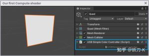
为了理解这一概念,让我们看看 USB_simple_color 着色器中由 Unity 自动声明的结构体吧。我们将从 appdata 开始:
struct appdata
{
    float4 vertex : POSITION;
    float2 uv : TEXCOORD0;
};
如我们所见,appdata 结构体中有两个向量,分别是 vertex 和 uv。“Vertex”后的是POSITION语义,这代表该向量储存了模型顶点在模型空间的位置信息。这些位置信息将在顶点着色器阶段通过 UnityObjectToClipPos(v.vertex) 函数变换到裁剪空间。
向量 uv 后的是 TEXCOORD0 语义,提供了纹理的 UV 坐标。
为什么向量 vertex 有四个维度(float4)?因为我们在该向量中存储的是 XYZW 值,其中 W 等于“1”,顶点则对应于空间中的一个位置。
在 v2f 结构体中我们可以找到与 appdata 中相同的向量,但 SV_POSITION 语义略有不同。虽然它的功能与 POSITION[n] 相同,但前缀为“SV_”(系统值)。
struct v2f
{
    float2 uv : TEXCOORD0;
    UNITY_FOG_COORDS(1)
    float4 vertex : SV_POSITION;
};
请注意,这些向量在顶点着色器阶段的连接方式如下:
v2f vert (appdata v)
{
    v2f o;
    o.vertex = UnityObjectToClipPos(v.vertex);
    o.uv = TRANSFORM_TEX(v.uv, _MainTex);
   ...
}“o.vertex”即顶点输出,对应我们在 v2f 结构体中声明的 vertex 向量;“v.vertex”即顶点输入,对应我们在 appdata 结构体中声明的 vertex 向量。这一逻辑同样适用于 uv 向量。
原文对照
A data type that we will use frequently in the creation of our shaders is “struct“. For those who know the C language, a struct is a compound data type declaration, which defines a grouped list of multiple elements of the same type and allows access to different variables through a single pointer. We will use structs to define both inputs and outputs in our shader. Its syntax is as follows:
struct name
{
    vector[n] name : SEMANTIC[n];
};
First, we declare the struct and then its name. Then we store the vector semantics inside the struct field for later use. The struct “name” corresponds to the name of the structure, the “vector” corresponds to the type of vector that we will use (e.g. float2, half4) to assign a semantic. Finally, “SEMANTIC” corresponds to the semantics that we will pass as input or output.
By default, Unity adds two struct functions, which are: appdata and v2f. Appdata corresponds to the “vertex input” and v2f refers to the “vertex output“.
The vertex input will be the place where we store our object properties (e.g. position of vertices, normals, etc.) as an “entrance” to take them to the “vertex shader stage”. Whereas, vertex output will be where we store the rasterized properties to take them to the “fragment shader stage”.
We can think of semantics as “access properties” of an object. According to the official Microsoft documentation:
A semantic is a chain connected to a shader input or output that transmits usage information of the intended use of a parameter.
We will exemplify using the POSITION[n] semantic.
In previous pages, we have talked about the properties of a primitive. As we already know, a primitive has its vertex position, tangents, normals, UV coordinates and color in the vertices. A semantic allows individual access to these properties, that is, if we declare a fourdimensional vector, and we pass it the POSITION[n] semantic then that vector will contain the primitive vertices position. Suppose we declare the following vector:
float4 pos : POSITION;It means that inside the four-dimensional vector called “pos”, we store the object vertices position in object-space.
The most common semantics that we use are:
- POSITION[n].
- TEXCOORD[n].
- TANGENT[n].
- NORMAL[n].
- COLOR[n].
struct vertexInput (e.g. appdata)
{
    float4 vertPos : POSITION;
    float2 texCoord : TEXCOORD0;
    float3 normal : NORMAL0;
    float3 tangent : TANGENT0;
    float3 vertColor: COLOR0;
};

struct vertexOutput (e.g. v2f)
{
    float4 vertPos : SV_POSITION;
    float2 texCoord : TEXCOORD0;
    float3 tangentWorld : TEXCOORD1;
    float3 binormalWorld : TEXCOORD2;
    float3 normalWorld : TEXCOORD3;
    float3 vertColor: COLOR0;
};
TEXCOORD[n] allows access to the UV coordinates of our primitive and has up to four dimensions (x, y, z, w).
TANGENT[n] gives access to the tangents of our primitive. If we want to create normal maps, it will be necessary to work with a semantic that has up to four dimensions as well.
Through NORMAL[n] we can access the normals of our primitive, and it has up to four dimensions. We must use this semantic if we want to work with lighting within our shader.
Finally, COLOR[n] allows us to access the color of the vertices of our primitive and has up to four dimensions like the rest. Generally, the vertex color corresponds to a white color (1, 1, 1, 1).
To understand this concept, we are going to look at the structures that have been declared automatically within our USB_simple_color shader. We will start with appdata.
struct appdata
{
    float4 vertex : POSITION;
    float2 uv : TEXCOORD0;
};
As we can see, there are two vectors within the structure: vertex and uv. “Vertex” has the POSITION semantic; this means that inside the vector, we are storing the position of the vertices of the object in object-space. These vertices are later transformed to clip-space in the vertex shader stage through the UnityObjectToClipPos(v.vertex) function.
The vector uv has the semantic TEXCOORD0, which gives access to the UV coordinates of the texture.
Why does the vertex vector have four dimensions (float4)? Because within the vector we are storing the values XYZW, where W equals “one” and vertices correspond to a position in space.
Within the v2f structure we can find the same vectors as in appdata, with a small difference in the SV_POSITION semantic, which fulfills the same function as POSITION[n], but has the prefix “SV_” (System Value).
struct v2f
{
    float2 uv : TEXCOORD0;
    UNITY_FOG_COORDS(1)
    float4 vertex : SV_POSITION;
};
Note that these vectors are being connected in the vertex shader stage as follows:
v2f vert (appdata v)
{
    v2f o;
    o.vertex = UnityObjectToClipPos(v.vertex);
    o.uv = TRANSFORM_TEX(v.uv, _MainTex);
   ...
}“o.vertex” is equal to the vertex output, that is, the vertex vector that has been declared in the v2f structure, while “v.vertex” is equal to the vertex input, that is, the vector vertex that has been declared in the appdata structure. This same logic applies to uv vectors.
![[udemy]在 Unity 中创建 RPG 游戏的终极指南-软件开发学习笔记](https://gamedevfan.cn/wp-content/uploads/2025/04/TheUltimateGuidetoCreatinganRPGGameinUnity.webp)
![[udemy]学习在 Unity 和 C# 中创建吸血鬼幸存者风格的游戏-软件开发学习笔记](https://gamedevfan.cn/wp-content/uploads/2025/04/LearnToCreateAVampireSurvivorsStyleGameinUnityC.webp)
![[udemy] 在 Godot 4 中创建完整的 2D 幸存者风格游戏-软件开发学习笔记](https://gamedevfan.cn/wp-content/uploads/2025/05/CreateaComplete2DSurvivorsStyleGameinGodot4.webp)
![[gamedev tv] RPG核心战斗力的创造者 :学习中级 Unity C# 编码-软件开发学习笔记](https://gamedevfan.cn/wp-content/uploads/2025/04/RPGCoreCombatCreatorLearnIntermediateUnityCCoding.png)
![[gamedev tv] 完成 Godot 3D:使用 Godot 4 开发您自己的 3D 游戏-软件开发学习笔记](https://gamedevfan.cn/wp-content/uploads/2025/05/CompleteGodot3DDevelopYourOwn3DGamesUsingGodot4.webp)


暂无评论内容