目录索引

译文
法线贴图是一种帮助我们在不增加模型顶点的前提下为模型表面生成更多细节的技术。
要想实现这个效果,物体表面的法线必须依照某种参考改变原本的方向。我们可以将每个顶点的法线要改变的方向存储到一个被称为切线空间的空间中,这种空间用于计算物体表面的光照。
![图片[1]-《Unity着色器圣经》6.0.1 | 法线贴图-软件开发学习笔记](https://gamedevfan.cn/wp-content/uploads/2025/05/image-82-1024x400.jpeg)
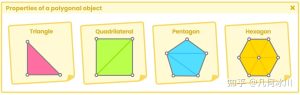
我们需要使用三个归一化向量来生成法线贴图,它们分别是切线(Tangent)、副切线(Binormal)和法线(Normal)。这三个向量组成了一个称为 TBN 的矩阵。
在本书的第 5.0.1 小节中,我们曾介绍了如何将法线通过 unity_ObjectToWorld 函数变换到世界空间中。类似的,我们将通过 TBN 矩阵转换坐标空间,从而将光照和法线贴图从世界空间转换到切空间。TBN 矩阵如下所示:
float4x4 TBN = float4x4
(
Tx, Ty, Tz, 0,
Bx, By, Bz, 0,
Nx, Ny, Nz, 0,
0, 0, 0, 0
);
在这个矩阵中,第一行对应切线的值,第二行对应副切线,第三行则对应法线。在具体实现中也必须按照此顺序来。
为了更好的理解这些概念,让我们创建一个名为 USB_ normal_map 的无光照着色器。我们将从往着色器中添加纹理属性开始:
Shader "USB/USB_normal_map"
{
    Properties
    {
        _MainTex ("Texture", 2D) = "white" {}
        _NormalMap ("Normal Map", 2D) = "white" {}
    }
    SubShader { ... }
}
在属性语义块中,我们声明了一个名为 _NormalMap 的2D类型的贴图属性,我们将通过该属性从 Unity 材质检查器中应用法线贴图。
接下来,我们需要添加能够链接属性与着色器程序的链接变量:
Pass
{
    CGPROGRAM
    ...
    sampler2D _MainTex;
    float4 _MainTex_ST;
    sampler2D _NormalMap;
    float4 _NormalMap_ST;
    ...
    ENDCG
}
现在,我们的法线贴图可以作为纹理在着色器程序中使用了。现在我们需要创建 TBN 矩阵,为此我们将从顶点输入(appdata)中通过 NORMAL 和 TANGENT 语义获取模型的法线和切线:
Pass
{
    CGPROGRAM
    ...
    struct appdata
    {
        float4 vertex : POSITION;
        float2 uv : TEXCOORD0;
        float3 normal : NORMAL;
        float4 tangent : TANGENT;
    };
    ...
    ENDCG
}
需要注意的一点是,appdata 中的法线和切线都位于模型空间,因此我们需要先将它们变换到世界空间,才能进一步将它们变换到切线空间。为了完成这一步,我们需要在顶点输入和输出关联它们,并将顶点输出传递到片元着色器中。所以,为了后续世界空间中的计算,我们需要将法线、切线和副切线添加到 v2f 结构体中。
Pass
{
    CGPROGRAM
    ...
    struct v2f
    {
        float4 vertex : SV_POSITION;
        float2 uv : TEXCOORD0;
        float2 uv_normal : TEXCOORD1;
        float3 normal_world : TEXCOORD2;
        float4 tangent_world : TEXCOORD3;
        float3 binormal_world : TEXCOORD4;
    };
    ...
    ENDCG
}
如上面的代码所示,我们无法在顶点输出中使用 NORMAL 和 TANGENT 语义,因为它们不存在于此阶段中。在这种情况下,我们就需要使用一种能够承载四维向量的语义,因此我们在上面的例子中选择了 TEXCOORD[n]。
我们不难发现每个属性的坐标系都有一个不同的 id,例如 uv_normal 的 id 配分配为TEXCOORD [1],binormal_world 的 id 为 4 等等。这些属性的 id 值必须不同,否则我们就会在重复的坐标系上执行操作。
为了将属性们从模型空间变换到世界空间,我们需要在顶点着色器中执行以下步骤:
v2f vert (appdata v)
{
    v2f o;
    o.vertex = UnityObjectToClipPos(v.vertex);
    o.uv = TRANSFORM_TEX(v.uv, _MainTex);

    // 为法线贴图添加平铺和偏移
    o.uv_normal = TRANSFORM_TEX(v.uv, _NormalMap);
    // 将法线变换到世界空间
    o.normal_world = normalize(mul(unity_ObjectToWorld, float4(v.normal, 0)));
    // 将切线变换到世界空间
    o.tangent_world = normalize(mul(v.tangent, unity_WorldToObject));
    // 计算法线与切线的叉乘
    o.binormal_world = normalize(cross(o.normal_world, o.tangent_world) * v.tangent.w);

    return o;
}
在上面的例子中,我们从通过“UnityCg.cginc”中包含的 TRANSFORM_TEX 函数为法线贴图的 UV 坐标添加平铺和偏移开始,接着用四维矩阵 unity_ObjectToWorld 乘以法线,将其从模型空间变换到世界空间,结果储存在被称为 normal_world 的四维向量中,并将在之后被传递到片元着色器中。
接着,我们同样用四维矩阵 unity_ObjectToWorld 乘以切线,将其变换到世界空间,再利用叉乘计算出垂直于法线和切线的副切线。我们将变换过的切线与计算得到的副切线分别存入 tangent_world 和 binormal_world 中。
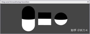
在 Direct3D 11 中,可能需要将顶点输出 v2f 初始化为“0”,以便在着色器中进行法线计算。如果不这样做,Unity 控制台中会出现警告(如下图所示),着色器还会显示与这一点有关的小错误。
![图片[2]-《Unity着色器圣经》6.0.1 | 法线贴图-软件开发学习笔记](https://gamedevfan.cn/wp-content/uploads/2025/05/image-81-1024x441.jpeg)
在这种情况下,我们必须在顶点着色器中使用 UNITY_INITIALIZE_OUTPUT 宏,如下所示:
v2f vert (appdata v)
{
    v2f o;
    UNITY_INITIALIZE_OUTPUT (v2f, o);
    o.vertex = UnityObjectToClipPos(v.vertex);
    ...
}
现在,我们已经在顶点着色器阶段连接好了输入和输出。接下来我们需要构建 TBN 矩阵,从而将法线贴图从世界空间转换到切线空间。这一过程将在片段着色器阶段完成。
在读取法线贴图时,我们必须考虑的一个点是:XYZW 坐标被存储在 RGBA 通道中,而 Unity 中的 RGBA 颜色通道的范围介于 0 到 1 之间。
理解这一概念非常重要,因为法线的范围将介于 -1 到 1 之间,为了从法线贴图中提取法线,我们需要使用下面的函数改变范围:
normal_map.rgb * 2 – 1;
为了说明上述操作,我们来做下面的练习: 如果我们将一个介于 0 到 1 之间的范围乘以 2,那么这个范围将变成 0 到 2。为什么呢?因为 0 乘以 2 等于 0,而 1 乘以 2 等于 2:
0 * 2 = 0 Minimum color
1 * 2 = 2 Maximum color
我们可以看到,我们改变了范围,现在它变成了 [0, 2]。接着,如果我们再减去 1,那么范围将变成 [-1, 1]。
0 – 1 = -1 Minimum color
2 – 1 = 1 Maximum color
执行此操作对我们的法线贴图正常工作至关重要。我们必须考虑的另一个因素是,法线贴图比法线纹理大得多,因此我们必须对其进行压缩,以减少 GPU 图形负载。
原文对照
A normal map is a technique that allows you to generate details about a surface without the need to add more vertices to the object.
To perform this process, the normals must change direction following some frame of reference. To do this, we can store each vertex within a space coordinate called tangentspace. This type of space is used for the calculation of illumination on the object surface.
To generate our normal map we have to use three normalized vectors, which correspond to tangents, binormals and normals. These three, together, form a matrix called TBN (T for tangent, B for binormal and N for normal).
In section 5.0.1 we talked about how to transform normals into world-space using the matrix unity_ObjectToWorld.
Similarly, we will use the TBN matrix to pass from one space to another, and thus, be able to transform both the lighting and our normal map, from world-space to tangent-space. The graphical representation of the TBN array is the following:
float4x4 TBN = float4x4
(
Tx, Ty, Tz, 0,
Bx, By, Bz, 0,
Nx, Ny, Nz, 0,
0, 0, 0, 0
);
In the matrix, the first row corresponds to tangent values, the second row to binormals and the third to normals. This same order must be followed in its implementation.
To illustrate these concepts, we will create a new Unlit Shader, which we will call USB_ normal_map. The application of the normal map will start by adding a texture property in our program.
Shader "USB/USB_normal_map"
{
    Properties
    {
        _MainTex ("Texture", 2D) = "white" {}
        _NormalMap ("Normal Map", 2D) = "white" {}
    }
    SubShader { ... }
}
In the properties’ field we have declared a 2D type texture property called _NormalMap, we will use this to apply our normal map dynamically, from the Inspector window.
Next, we must add the variables and/or connection vectors corresponding to the declared property.
Pass
{
    CGPROGRAM
    ...
    sampler2D _MainTex;
    float4 _MainTex_ST;
    sampler2D _NormalMap;
    float4 _NormalMap_ST;
    ...
    ENDCG
}
Now, our normal map can be used inside the shader as a texture. Therefore, we must create the TBN matrix, for this, we will extract the normals and tangents from our object to the vertex input, called appdata, and then implement the NORMAL and TANGENT semantics.
Pass
{
    CGPROGRAM
    ...
    struct appdata
    {
        float4 vertex : POSITION;
        float2 uv : TEXCOORD0;
        float3 normal : NORMAL;
        float4 tangent : TANGENT;
    };
    ...
    ENDCG
}
A factor to consider is that, up to this point, both normals and tangents are in objectspace, and we need them to be transformed into world-space before being converted into tangent-space. To do this, we have to connect them in the vertex shader stage, and then pass the vertex output to the fragment shader stage. Then, we must add the normal, tangent, and binormal coordinates in the struct v2f for their calculation in world-space in the following manner:
Pass
{
    CGPROGRAM
    ...
    struct v2f
    {
        float4 vertex : SV_POSITION;
        float2 uv : TEXCOORD0;
        float2 uv_normal : TEXCOORD1;
        float3 normal_world : TEXCOORD2;
        float4 tangent_world : TEXCOORD3;
        float3 binormal_world : TEXCOORD4;
    };
    ...
    ENDCG
}
As mentioned above, you cannot use the semantics NORMAL or TANGENT within the vertex output, this is because they do not exist for this process. In this case, we must use semantics that can store up to four dimensions in each of their coordinates. This is why we used the semantics TEXCOORD[n] in the example above.
Now, if we pay attention, we will notice that each of the properties has a coordinate with a different ID, e.g., uv_normal is assigned to TEXCOORD with its index in [1] while binormal_ world has the index [4]. It is essential that the IDs have different values because, otherwise, we would perform operations on a duplicate coordinate system.
To transform the properties from object-space to world-space, we go to the vertex shader stage and perform the following operation:
v2f vert (appdata v)
{
    v2f o;
    o.vertex = UnityObjectToClipPos(v.vertex);
    o.uv = TRANSFORM_TEX(v.uv, _MainTex);

    // add tiling and offset to the normal map
    o.uv_normal = TRANSFORM_TEX(v.uv, _NormalMap);
    // transform the normals to world-space
    o.normal_world = normalize(mul(unity_ObjectToWorld, float4(v.normal, 0)));
    // transform tangents to world-space
    o.tangent_world = normalize(mul(v.tangent, unity_WorldToObject));
    // calculate the cross product between normals and tangents
    o.binormal_world = normalize(cross(o.normal_world, o.tangent_world) * v.tangent.w);

    return o;
}
In the example above, we have started the operation by adding tiling and offset to the normal map UV coordinates through the TRANSFORM_TEX function, which is included in “UnityCg.cginc”. Then, we multiply the four-dimensional matrix called unity_ObjectToWorld by the normals input to transform their space coordinates from object-space to worldspace. The multiplication result is stored within the normals output called normal_world, which we will use later for the per-pixel calculation in the fragment shader stage.
Next, we multiply the tangents by the matrix unity_WorldToObject to inversely transform their coordinates from world-space to object-space, and finally calculate a perpendicular vector between the normals and tangents, using the cross function, which, refers to cross product. Its result is known as binormal, which is why we store it within the output binormal_world.
It is possible that in Direct3D 11 it is necessary to initialize the vertex output v2f at “zero” to carry out the calculation of the normals in our shader. To confirm this, a warning will appear in the Unity console, and in addition, the shader will show a small error related to this point.
In this case, we have to use the macro UNITY_INITIALIZE_OUTPUT within the vertex shader as follows:
v2f vert (appdata v)
{
    v2f o;
    UNITY_INITIALIZE_OUTPUT (v2f, o);
    o.vertex = UnityObjectToClipPos(v.vertex);
    ...
}
Now we have our inputs and outputs connected in the vertex shader stage. What we need to do next is generate the TBN array to transform the coordinates of the normal map from world-space to tangent-space. This process will be carried out in the fragment shader stage.
One factor we must consider when reading our normal map is that the XYZW coordinates are embedded within the RGBA channels. The RGBA colors or channels in Unity, have a range between zero and one (0, 1), this means that, for example, the minimum value of the color red is “zero” and the maximum is “one” [0, 1].
It is essential to understand this concept since, if we want to extract the normals from the normal map, these will have a color range between minus one and one [-1, 1] so, the first thing we must do is change the scale of the range using the following function:
normal_map.rgb * 2 – 1;
To illustrate the above operation, we will do the following exercise: If we multiply a range between zero and one, by two, then the new value of the range will be between zero and two, why? Because zero times two, is zero, and one times two, is two.
0 * 2 = 0 Minimum color
1 * 2 = 2 Maximum color
As we can see, we have changed the range, now it goes from zero to two [0, 2], however, if we subtract one, then our range will go from minus one to one [-1, 1].
0 – 1 = -1 Minimum color
2 – 1 = 1 Maximum color
Performing this operation is essential for our normal map to work correctly. Another factor that we must consider is that normal maps are much heavier than a normal texture, which is why we have to compress them to reduce their GPU graphic load.
![[udemy]在 Unity 中创建 RPG 游戏的终极指南-软件开发学习笔记](https://gamedevfan.cn/wp-content/uploads/2025/04/TheUltimateGuidetoCreatinganRPGGameinUnity.webp)
![[udemy]学习在 Unity 和 C# 中创建吸血鬼幸存者风格的游戏-软件开发学习笔记](https://gamedevfan.cn/wp-content/uploads/2025/04/LearnToCreateAVampireSurvivorsStyleGameinUnityC.webp)
![[udemy] 在 Godot 4 中创建完整的 2D 幸存者风格游戏-软件开发学习笔记](https://gamedevfan.cn/wp-content/uploads/2025/05/CreateaComplete2DSurvivorsStyleGameinGodot4.webp)
![[gamedev tv] RPG核心战斗力的创造者 :学习中级 Unity C# 编码-软件开发学习笔记](https://gamedevfan.cn/wp-content/uploads/2025/04/RPGCoreCombatCreatorLearnIntermediateUnityCCoding.png)
![[gamedev tv] 完成 Godot 3D:使用 Godot 4 开发您自己的 3D 游戏-软件开发学习笔记](https://gamedevfan.cn/wp-content/uploads/2025/05/CompleteGodot3DDevelopYourOwn3DGamesUsingGodot4.webp)


暂无评论内容