目录索引

译文
环境反射与高光反射的原理类似,不同在于后者仅被主光源影响,而环境光反射被照射到表面上的每一束光线影响。
![图片[1]-《Unity着色器圣经》7.0.5 | 环境反射-软件开发学习笔记](https://gamedevfan.cn/wp-content/uploads/2025/05/image-95-1024x396.jpeg)
实时计算这种类型的反射需要占用大量GPU资源,因此一种名为立方贴图(Cubemap)的技术诞生了。在本书的第 3.0.6 小节中,我们曾提到了“Cube”属性,指代的就是这一种贴图。
在 Unity 中,我们可以通过反射探针(Reflection Probe)组件生成立方贴图。这个组件类似于一台相机,可以以球体的视角无死角地捕捉周围的环境,并生成一张可以用作反射贴图的 Cube 类型的贴图。
![图片[2]-《Unity着色器圣经》7.0.5 | 环境反射-软件开发学习笔记](https://gamedevfan.cn/wp-content/uploads/2025/05/image-94-1024x358.jpeg)
让我们创建一个名为 USB_cubemap_reflection 的无光照着色器,一起探索环境反射背后的实现细节吧。
首先,创建一个名叫 AmbientReflection 的函数,我们的程序如下所示:
Shader "USB/USB_cubemap_reflection"
{
    Properties { … }
SubShader
{
    Pass
{
    CGPROGRAM
    …
    // 在程序中加入函数
    float3 AmbientReflection () { … }
    …
    // 环境反射函数的内部结构
    float3 AmbientReflection (
    samplerCUBE colorRefl,
    float reflectionInt,
    half reflectionDet,
    float3 normal,
    float3 viewDir,
    float reflectionExp
    )
    {
        float3 reflection_world = reflect(viewDir, normal);
        float4 cubemap = texCUBElod(colorRefl, float4(reflection_world, reflectionDet));
        return reflectionInt * cubemap.rgb * (cubemap.a * reflectionExp);
    }
}
函数的第一个参数声明了一个 Cube 类型贴图的采样器(colorReflRGBA),这需要创建一个此类属性。然后,我们可以找到一个变量来修改反射强度(reflectionInt),其中最大值为“1”,最小值为“0”。第三个参数对应一个名为“reflectionDet”([1, 9])的中等精度变量,该变量可以增加或减少 samplerCUBE 的像素密度。
请注意,reflaectionDet 变量已经通过以下方式被包含在了 texCUBElod 方法内:
texCUBElod(colorRefl, float4(reflection_world, reflectionDet));

// float4 texCUBE lod(samplerCUBE samp, float4 s)
// s.xyz = reflection coordinates
// s.w = texel density
“texCUBlod”方法有两个默认输入变量,第一个代表我们要用于贴图的采样器 samplerCUBE,第二个代表了一个被分为两个部分的四维向量,其中向量的前三个值(XYZ)代表世界空间下的反射,最后一个值(W)代表了 samplerCUBE 的像素细节程度。
在高光反射中,我们必须计算世界空间下的法线与视线方向,因此,我们必须将这些向量作为参数输入函数中。最后,函数的最后一个输入参数名为“reflectionExp”,代表高光贴图颜色的曝光程度。
在计算反射时我们经常使用到的一个函数叫“reflect”。该函数被包含在 Cg 和 HLSL 下:
float3 reflect (float3 i, float3 n)
{
    return i - 2.0 * n * dot(n, i);
}

float3 reflection_world = reflect(viewDir, normal);
变量 [i] 代表了入射值(即视线方向),而 [n] 代表了模型法线。
需要注意的是,在 reflect 函数的内部运算中,入射值是按照反射点的方向计算的,这将使反射图在图形上发生变化,就好像我们通过凹透镜看到的反射一样。为了解决这个问题,我们必须将入射值设为负数。
现在我们理解了许多操作,我们将开始在片元着色器中一步步进行实现。让我们先创建一个三维向量,并传入 AmbientReflection 函数,如下所示:
float3 AmbientReflection() { ... }

fixed4 frag (v2f i) : SV_Target
{
    fixed4 col = tex2D(_MainTex, i.uv);
    half3 reflection = AmbientReflection(0, 0, 0, 0, 0, 0);

    return col;
}
我们已经知道,AmbientReflection 函数的第一个参数代表了立方类型的反射颜色,所以我们将转到着色器属性中,声明纹理以及强度、细节和曝光值。
Shader "USB/USB_cubemap_reflection"
{
    Properties
    {
        _MainTex ("Texture", 2D) = "white" {}

        _ReflectionTex ("Reflection Texture", Cube) = "white" {}
        _ReflectionInt ("Reflection Intensity", Range(0, 1)) = 1
        _ReflectionMet ("Reflection Metallic", Range(0, 1)) = 0
        _ReflectionDet ("Reflection Detail", Range(1, 9)) = 1
        _ReflectionExp ("Reflection Exposure", Range(1, 3)) = 1
    }
    SubShader { ... }
}
在这些已声明了的属性中,我们可以找到不被包含在 AmbientReflection 函数中的 _ReflectionMet 属性。正如该属性的名字所示,它控制了反射的光泽程度,从而模拟金属表面。
我们将继续创建这些属性的链接变量:
CGPROGRAM
...
sampler2D _MainTex;
float4 _MainTex_ST;
samplerCUBE _ReflectionTex;
float _ReflectionInt;
half _ReflectionDet;
float _ReflectionExp;
float _ReflectionMet;
...
ENDCG
由于纹理采样发生在 AmbientReflection 函数中,因此我们可以直接将 _ReflectionTex 属性作为函数的第一个参数传入函数中。
fixed4 frag (v2f i) : SV_Target
{
    fixed4 col = tex2D(_MainTex, i.uv);
    // 加入立方贴图
    half3 reflection = AmbientReflection(_ReflectionTex, 0, 0, 0, 0, 0);

    return col;
}
我们也可以传入第二与第三个参数,即反射的强度 reflectionInt(reflection intensity)与反射的细节 reflectionDet(reflection detail)。
fixed4 frag (v2f i) : SV_Target
{
    fixed4 col = tex2D(_MainTex, i.uv);
    // 加入反光的强度和细节
    half3 reflection = AmbientReflection(_ReflectionTex, _ReflectionInt, _ReflectionDet, 0, 0, 0);

    return col;
}
第四与第五个参数代表世界空间下的法线与视线方向。为此,就像我们曾在计算高光反射中所做的那样,在顶点输入中包含法线,然后在顶点输出中声明法线和视线方向。
// 顶点输入
struct appdata
{
    float4 vertex : POSITION;
    float2 uv : TEXCOORD0;
    float3 normal : NORMAL;
};

// 顶点输出
struct v2f
{
    float2 uv : TEXCOORD0;
    float4 vertex : SV_POSITION;
    float3 normal_world : TEXCOORD1;
    float3 vertex_world : TEXCOORD2;
};现在我们可以在顶点着色器阶段将法线从模型空间变换到世界空间。
v2f vert (appdata v)
{
    v2f o;
    o.vertex = UnityObjectToClipPos(v.vertex);
    o.uv = TRANSFORM_TEX(v.uv, _MainTex);
    o.normal_world = normalize(mul(unity_ObjectToWorld, float4(v.normal, 0))).xyz;
    o.vertex_world = mul(unity_ObjectToWorld, v.vertex);

    return o;
}
回到 AmbientReflection 函数,我们创建了一个新的向量,并赋上了法线的值,然后进行视线方向计算。不过这次,我们直接使用 UnityCg.cginc 中包含的 UnityWorldSpaceViewDir 函数,该函数对摄像机位置和对象顶点进行了计算。
// UnityCg.cginc 的内置函数
inline float3 UnityWorldSpaceViewDir( in float3 worldPos)
{
return _WorldSpaceCameraPos.xyz - worldPos;
}
// 我们的函数
fixed4 frag (v2f i) : SV_Target
{
fixed4 col = tex2D(_MainTex, i.uv);
half3 normal = i.normal_world;
half3 viewDir = normalize(UnityWorldSpaceViewDir(i.vertex_world));
// we add the normals and view direction
half3 reflection = AmbientReflection(_ReflectionTex, _ReflectionInt, _ReflectionDet, normal, -viewDir, 0);
return col;
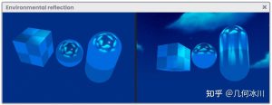
}仔细一看,我们会发现第五个参数(即视线方向 -viewDir)被加上了一个负号,这是为什么?在这种情况下,将该值设为负数就能使反射完美地发挥作用(如下图所示)。
![图片[3]-《Unity着色器圣经》7.0.5 | 环境反射-软件开发学习笔记](https://gamedevfan.cn/wp-content/uploads/2025/05/image-93-1024x316.jpeg)
最后,需要添加与反射曝光相对应的第六个参数,并将总反射值添加到主纹理 (_MainTex) 的 RGB 颜色中。
fixed4 frag (v2f i) : SV_Target
{
    fixed4 col = tex2D(_MainTex, i.uv);
    half3 normal = i.normal_world;
    half3 viewDir = normalize(UnityWorldSpaceViewDir(i.vertex_world));
    // 加入曝光
    half3 reflection = AmbientReflection(_ReflectionTex, _ReflectionInt, _ReflectionDet, normal, -viewDir, _ReflectionExp);

    col.rgb *= reflection + _ReflectionMet;
    return col;
}
在上面的例子中,我们将RGB形式的贴图颜色与反射相乘,并将结果与范围为 [0,1] 的 _ReflectionMet 属性相加。想要理解这个操作,我们需要注意另一个范围与之相同的属性 _ReflectionInt 。
由于反射向量乘以主纹理颜色 col.rgb,因此得到的颜色将是金属表面的颜色。我们用 _ReflectionMet 属性与结果相加,目的是淡化表面的最终颜色,从而获得反射变化。
另一种实现环境反射的方式是通过 UNITY_SAMPLE_TEXCUBE 函数,该函数将自动分配场景中配置的环境反射,这意味着如果我们在照明窗口(Lighting)中配置了天空盒,那么反射将作为纹理保存在着色器中,我们可以立即使用它,而无需独立生成 Cubemap 纹理。
fixed4 frag (v2f i) : SV_Target
{
    fixed4 col = tex2D(_MainTex, i.uv);
    half3 normal = i.normal_world;
    half3 viewDir = normalize(UnityWorldSpaceViewDir(i.vertex_world));
    half3 reflect_world = reflect(-viewDir, normal);
    // 该过程表示上面的部分已被函数替换
    // UNITY_SAMPLE_TEXCUBE
    half3 reflectionData = UNITY_SAMPLE_TEXCUBE(unity_SpecCube0, reflect_ world );
    half3 reflectionColor = DecodeHDR(reflectionData , unity_SpecCube0_ HDR);

    col.rgb = reflectionColor;
    return col;
}
内部变量 unity_SpecCube[n] 包含了 Unity 默认反射探针(Reflection Probe)的数据。
UNITY_SAMPLE_TEXCUBE 宏使用反射坐标(reflect_world)采样了数据,将其通过 UnityCg.cginc 内置的 DecodeHDR 函数解码为HDR形式的颜色
该操作使实现该类型的反射更加简单,但对最终效果的可控制部分较少。
原文对照
Environmental reflection occurs similarly to specular reflection. The difference is that the latter is affected only by the main light source, while ambient reflection is affected by every light ray that impacts the surface.
Given its nature, calculating this type of reflection in real time uses a lot of GPU power, instead, we can use a Cubemap type texture. In chapter one, section 3.0.6, we mentioned the Cube property, which refers precisely to this type of texture.
In Unity, we can generate Cubemaps using the Reflection Probe component. This object works similar to a camera, which captures a spherical view of its surroundings in all directions and then generates a Cube-type texture that we can use as a reflection map.
To see the implementation of this type of reflection in detail, we will create a new Unlit Shader called USB_cubemap_reflection.
Let’s start by creating a function called AmbientReflection and include it in our program as follows:
Shader "USB/USB_cubemap_reflection"
{
    Properties { … }
SubShader
{
    Pass
{
    CGPROGRAM
    …
    // we add the function in the program
    float3 AmbientReflection () { … }
    …
    // internal structure of the AmbientReflection function
    float3 AmbientReflection (
    samplerCUBE colorRefl,
    float reflectionInt,
    half reflectionDet,
    float3 normal,
    float3 viewDir,
    float reflectionExp
    )
    {
        float3 reflection_world = reflect(viewDir, normal);
        float4 cubemap = texCUBElod(colorRefl, float4(reflection_world, reflectionDet));
        return reflectionInt * cubemap.rgb * (cubemap.a * reflectionExp);
    }
}
The first argument declared in the previous function corresponds to a sampler for a Cube type texture (colorReflRGBA); this involves the creation of a property of this type. Then we can find a variable that will modify the reflection intensity (reflectionInt) where the maximum value is “one” and the minimum “zero”. The third argument corresponds to a mediumprecision variable called “reflectionDet” ([1, 9]). This variable increases or decreases the texel density of the samplerCUBE.
Note that reflectionDet has been included in the texCUBElod method as follows:
texCUBElod(colorRefl, float4(reflection_world, reflectionDet));

// float4 texCUBE lod(samplerCUBE samp, float4 s)
// s.xyz = reflection coordinates
// s.w = texel density
The “texCUBElod” method has two default arguments: the first refers to the samplerCUBE that we are going to use as a texture, and the second corresponds to a four-dimensional vector that has been divided into two parts; the first three values of the vector correspond to the reflection coordinates in world-space (XYZ), while the last value corresponds to the level of detail of the texels of the samplerCUBE (W).
As in specular reflection, we must calculate both the normals and the view direction in world-space, for this reason, we have included these vectors as arguments in the function. Finally, as a final argument, we can find a variable called “reflectionExp”. This refers to the reflection map color exposure.
A function that we will frequently use in the reflection calculation is “reflect”. This operation included in both Cg and HLSL is composed as follows:
float3 reflect (float3 i, float3 n)
{
    return i - 2.0 * n * dot(n, i);
}

float3 reflection_world = reflect(viewDir, normal);
Argument [i] refers to the incidence value, that is, the view direction, while [n] refers to the object normals.
It should be noted that in the internal operation of the reflect function, the incidence value is being calculated in the direction of the reflection point, which will graphically turn the reflection map as if we were seeing the reflection through a concave lens. To solve this, we have to make the incidence value negative.
Now that we understand a great deal of the operation, we will start implementing it in the fragment shader stage. To do this we will create a three-dimensional vector and pass it through the AmbientReflection function as follows:
float3 AmbientReflection() { ... }

fixed4 frag (v2f i) : SV_Target
{
    fixed4 col = tex2D(_MainTex, i.uv);
    half3 reflection = AmbientReflection(0, 0, 0, 0, 0, 0);

    return col;
}
As we already know, the first argument in the function corresponds to the Cube type reflection color, so we will go to our shader properties and declare the texture along with the intensity, detail, and exposure variables.
Shader "USB/USB_cubemap_reflection"
{
    Properties
    {
        _MainTex ("Texture", 2D) = "white" {}

        _ReflectionTex ("Reflection Texture", Cube) = "white" {}
        _ReflectionInt ("Reflection Intensity", Range(0, 1)) = 1
        _ReflectionMet ("Reflection Metallic", Range(0, 1)) = 0
        _ReflectionDet ("Reflection Detail", Range(1, 9)) = 1
        _ReflectionExp ("Reflection Exposure", Range(1, 3)) = 1
    }
    SubShader { ... }
}
Among the properties that have been declared, we can find _ReflectionMet which has not been included in the AmbientReflection function. As the name says, we use this property to control the reflection shininess and thus emulate a metal surface.
We will continue to generate the connection variables for these properties.
CGPROGRAM
...
sampler2D _MainTex;
float4 _MainTex_ST;
samplerCUBE _ReflectionTex;
float _ReflectionInt;
half _ReflectionDet;
float _ReflectionExp;
float _ReflectionMet;
...
ENDCG
Since texture sampling occurs within the AmbientReflection function, we can pass the _ ReflectionTex property directly as the first argument in the function statement.
fixed4 frag (v2f i) : SV_Target
{
    fixed4 col = tex2D(_MainTex, i.uv);
    // let’s add the cubemap
    half3 reflection = AmbientReflection(_ReflectionTex, 0, 0, 0, 0, 0);

    return col;
}
We can also add the second and third arguments to the function, since these correspond to reflectionInt and reflectionDet.
fixed4 frag (v2f i) : SV_Target
{
    fixed4 col = tex2D(_MainTex, i.uv);
    // we add the intensity and detail of the reflection
    half3 reflection = AmbientReflection(_ReflectionTex, _ReflectionInt, _ReflectionDet, 0, 0, 0);

    return col;
}
The fourth and fifth arguments correspond to the normals and the view direction, both in world-space. For this, we carry out exactly the same operation that we performed in the specular reflection, that is, we have to include the normals in the vertex input and then declare both the normals and the view direction in the vertex output.
// vertex input
struct appdata
{
    float4 vertex : POSITION;
    float2 uv : TEXCOORD0;
    float3 normal : NORMAL;
};

// vertex output
struct v2f
{
    float2 uv : TEXCOORD0;
    float4 vertex : SV_POSITION;
    float3 normal_world : TEXCOORD1;
    float3 vertex_world : TEXCOORD2;
};
Now we can simply transform their space coordinates from object-space to world-space in the vertex shader stage.
v2f vert (appdata v)
{
    v2f o;
    o.vertex = UnityObjectToClipPos(v.vertex);
    o.uv = TRANSFORM_TEX(v.uv, _MainTex);
    o.normal_world = normalize(mul(unity_ObjectToWorld, float4(v.normal, 0))).xyz;
    o.vertex_world = mul(unity_ObjectToWorld, v.vertex);

    return o;
}
Continuing with the AmbientReflection function, we create a new vector in which we assign the normals and then carry out the view direction calculation, however, this time we will use the UnityWorldSpaceViewDir function included in UnityCg.cginc, which is equivalent to the camera position and object vertices calculation.
// included function in UnityCg.cginc
inline float3 UnityWorldSpaceViewDir( in float3 worldPos)
{
     return _WorldSpaceCameraPos.xyz - worldPos;
}
// our function
fixed4 frag (v2f i) : SV_Target
{
    fixed4 col = tex2D(_MainTex, i.uv);
    half3 normal = i.normal_world;
    half3 viewDir = normalize(UnityWorldSpaceViewDir(i.vertex_world));
    // we add the normals and view direction
    half3 reflection = AmbientReflection(_ReflectionTex, _ReflectionInt, _ReflectionDet, normal, -viewDir, 0);

    return col;
}
Looking closely, we notice that the fifth argument; corresponding to the view direction (-viewDir), has been included in a negative form, basically, in the direction of the incidence vector, why is this? Making its value negative will allow the reflection to work perfectly for this case.
As a final operation, it is necessary to add the sixth argument corresponding to the reflection exposure, and in addition, add the total reflection to the RGB color of the main texture (_MainTex).
fixed4 frag (v2f i) : SV_Target
{
    fixed4 col = tex2D(_MainTex, i.uv);
    half3 normal = i.normal_world;
    half3 viewDir = normalize(UnityWorldSpaceViewDir(i.vertex_world));
    // we add the exposure
    half3 reflection = AmbientReflection(_ReflectionTex, _ReflectionInt, _ReflectionDet, normal, -viewDir, _ReflectionExp);

    col.rgb *= reflection + _ReflectionMet;
    return col;
}
In the example above, we multiply the texture color in RGB by the reflection and then add the property _ReflectionMet which corresponds to a range between zero and one [0, 1]. To understand this operation, we must pay attention to the property _ReflectionInt which is a range as well.
Since the reflection vector is being multiplied to col.rgb, the resulting color will be that of a metallic surface. Now, we add it to _ReflectionMet to lighten the final color of the surface and thus obtain reflection variations.
A different way of creating reflection is through the function UNITY_SAMPLE_TEXCUBE. This automatically assigns the environmental reflection that is configured in our scene, this means that, if we have configured a skybox from the lighting window then the reflection will be saved as a texture within our shader, and we can use it immediately without the need to independently generate a Cubemap texture.
fixed4 frag (v2f i) : SV_Target
{
    fixed4 col = tex2D(_MainTex, i.uv);
    half3 normal = i.normal_world;
    half3 viewDir = normalize(UnityWorldSpaceViewDir(i.vertex_world));
    half3 reflect_world = reflect(-viewDir, normal);
    // the process mentioned above is replaced by the function
    // UNITY_SAMPLE_TEXCUBE
    half3 reflectionData = UNITY_SAMPLE_TEXCUBE(unity_SpecCube0, reflect_ world );
    half3 reflectionColor = DecodeHDR(reflectionData , unity_SpecCube0_ HDR);

    col.rgb = reflectionColor;
    return col;
}
The internal variable unity_SpecCube[n] contains the data of the Unity default Reflection Probe object.
The macro UNITY_SAMPLE_TEXCUBE samples this data using the reflection coordinates (reflect_world) and then decodes the colors in HDR through the DecodeHDR function, which is included in UnityCg.cginc.
This operation makes it easier to implement this type of reflection but gives less control over the final result.
![[udemy]在 Unity 中创建 RPG 游戏的终极指南-软件开发学习笔记](https://gamedevfan.cn/wp-content/uploads/2025/04/TheUltimateGuidetoCreatinganRPGGameinUnity.webp)
![[udemy]学习在 Unity 和 C# 中创建吸血鬼幸存者风格的游戏-软件开发学习笔记](https://gamedevfan.cn/wp-content/uploads/2025/04/LearnToCreateAVampireSurvivorsStyleGameinUnityC.webp)
![[udemy] 在 Godot 4 中创建完整的 2D 幸存者风格游戏-软件开发学习笔记](https://gamedevfan.cn/wp-content/uploads/2025/05/CreateaComplete2DSurvivorsStyleGameinGodot4.webp)
![[gamedev tv] RPG核心战斗力的创造者 :学习中级 Unity C# 编码-软件开发学习笔记](https://gamedevfan.cn/wp-content/uploads/2025/04/RPGCoreCombatCreatorLearnIntermediateUnityCCoding.png)
![[gamedev tv] 完成 Godot 3D:使用 Godot 4 开发您自己的 3D 游戏-软件开发学习笔记](https://gamedevfan.cn/wp-content/uploads/2025/05/CompleteGodot3DDevelopYourOwn3DGamesUsingGodot4.webp)


暂无评论内容