目录索引

译文
现在我们已经理解了坐标空间的变换流程,我们可以回到先前创建的 USB_shadow_map 着色器中创建一个名为 NDCToUV 的函数。该函数表示从NDC空间变换到UV空间的过程,并将在顶点着色器阶段被使用,因此我们需要在该阶段之前声明它。
// 在顶点着色器阶段前声明NDCToUV函数
float4 NDCToUV(float4 clipPos)
{
    float4 uv = clipPos;
    uv.xy = float2(uv.x, uv.y) + uv.w;
    uv.xy = float2(uv.x / uv.w, uv.y / uv.w) * 0.5;
    return uv;
}

// 顶点着色器阶段
v2f vert(appdata v) { … }上面的代码中,NDCToUV 函数的返回类型为 float4,这代表一个四维向量(具有 XYZW 分量)。
在该函数中,我们使用了一个新声明的名为 clipPos 的四维向量,其代表了顶点的输出位置,即 UnityObjectToClipPos(v.vertex) 函数的结果。
该函数将上一小节所提到的数学计算转换成了代码。尽管如此,该操作并不完整,因为我们尚未将实现该函数所需的一些因素考虑在内。这些因素包括我们将在哪个平台编译我们的代码和偏移半像素(half-texel offset)。
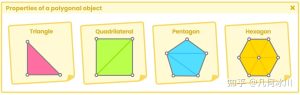
值得一提的是 OpenGL 和 Direct3D 之间存在坐标上的差异。如下图所示,Direct3D 的 UV 坐标的原点在左上角,而 OpenGL 的在左下角。
![图片[1]-《Unity着色器圣经》8.0.4 | 阴影实现-软件开发学习笔记](https://gamedevfan.cn/wp-content/uploads/2025/05/image-103-1024x359.jpeg)
这个因素在实现该函数时造成了一些问题,因为运算的结果可能因平台而异。为了解决这个问题,Unity 提供了一个名为 _ProjectionParams 的内置变量来帮助开发者纠正坐标差异。
_ProjectionParams 是一个四维向量,根据坐标的不同会有不同的值。例如,_ProjectionParams.x 可以是“1”或“-1”,具体是哪个取决于平台是否有翻转的变换矩阵(flipped transformation matrix)。在 Direct3D 中,_ProjectionParams.y 存有相机近裁平面的距离(Znear)而 _ProjectionParams.z 存有远裁平面的距离(Zfar),_ProjectionParams.w 存有 1/Zfar 运算。
在本例中,我们将使用 _ProjectionParams.x,因为我们只需根据 V 坐标的起始点转动 V 坐标即可。回顾图 8.0.4a 就会发现 U 坐标无论在哪个平台上编译,都会保持其位置不变。
根据上述概念,如果着色器是通过 OpenGL 编译的,_ProjectionParams.x 的值将等于“1”;而如果是通过 Direct3D 编译的,_ProjectionParams.x 的值将等于“-1”。考虑到这一因素,我们的操作如下:
float4 NDCToUV(float4 clipPos)
{
    float4 uv = clipPos;
    uv.xy = float2(uv.x, uv.y * _ProjectionParams.x) + uv.w;
    uv.xy = float2(uv.x / uv.w, uv.y / uv.w) * 0.5;
    return uv;
}
我们可以看到,上述代码中 UV 的 V 坐标乘上了 _ProjectionParams.x。这样,如果我们的着色器是在 Direct3D 中编译的,我们就可以翻转矩阵,现在我们只需要添加半像素偏移(half-texel offset)即可。
在 Unity 中有一个名为 UNITY_HALF_TEXEL_OFFSET 的宏,它适用于需要从纹理到像素调整贴图位移的平台。为了进行位移,我们将使用内部变量 _ScreenParams,它与 _ProjectionParams 同样是一个四维向量,每个分量都有不同的值。
我们要使用的通道是 _ScreenParams.zw ,其中 Z 分量等于 1.0f + 1.0f / 屏幕宽度,W 分量等于 1.0f + 1.0f / 屏幕高度。
考虑了半像素偏移的因素之后,我们的函数如下所示:
float4 NDCToUV(float4 clipPos)
{
    float4 uv = clipPos;
    #if defined(UNITY_HALF_TEXEL_OFFSET )
        uv.xy = float2(uv.x, uv.y * _ProjectionParams.x) + uv.w * _ScreenParams.zw;
    #else
        uv.xy = float2(uv.x, uv.y * _ProjectionParams.x) + uv.w;
    #endif
        uv.xy = float2(uv.x / uv.w, uv.y / uv.w) * 0.5;
    return uv;
}
至此,阴影的 UV 坐标已经可以完美地运行了。现在,我们必须在顶点着色器阶段使用该函数,为此我们将顶点输出中的 shadowCoord 等于 NDCToUV 函数,并将输出的顶点作为参数传入函数中;那些被剪切的顶点。
float4 NDCToUV() { ... }

v2f vert (appdata v)
{
    v2f o;
    o.vertex = UnityObjectToClipPos(v.vertex);
    o.uv = TRANSFORM_TEX(v.uv, _MainTex);
    o.shadowCoord = NDCToUV(o.vertex);

    return o;
}
此时 shadowCoords 获取了投影坐标,现在我们可以将其用作 _ShadowMapTexture 的 UV 坐标了。
我们已经知道,tex2D 函数需要两个参数:纹理及其 UV 坐标。我们可以使用该函数在片元着色器中生成阴影。
fixed4 frag (v2f i) : SV_Target
{
    fixed4 col = tex2D(_MainTex, i.uv);
    // 将阴影贴图存储在shadow变量中
    fixed shadow = tex2D(_ShadowMapTexture, i.shadowCoord).a;
    col.rgb *= shadow;

    return col;
}
在上面的代码中,我们创建了一个名为 shadow 的 fixed 类型的变量,用于保存 _ShadowMapTexture 的采样值。
这里的 shadow 只有一维,为什么呢?
我们必须记住的是:阴影纹理只有黑色与白色两种颜色。因此,我们只在 shadow 变量中存储了 Alpha 通道的结果,因为它为我们提供了 [0, 1] 的范围。
原文对照
Now that we understand the coordinate transformation process, we can go back to our shader USB_shadow_map to generate a function that we will call NDCToUV. This will be responsible for transforming from Normalized Device Coordinates to UV coordinates. This function will be used in the vertex shader stage, so it will have to be declared above that stage.
// declare NDCToUV above the vertex shader stage
float4 NDCToUV(float4 clipPos)
{
    float4 uv = clipPos;
    uv.xy = float2(uv.x, uv.y) + uv.w;
    uv.xy = float2(uv.x / uv.w, uv.y / uv.w) * 0.5;
    return uv;
}

// vertex shader stage
v2f vert(appdata v) { … }
The previous example has declared the NDCToUV function to be type float4, that is, a fourdimensional vector (XYZW).
A new four-dimensional vector called clipPos has been used as an argument referring to the vertices output position; the result of the UnityObjectToClipPos(v.vertex) function.
Inside the function, the mathematical operation mentioned in the previous section is then translated into code. Despite this, the operation is not complete because there are some factors that we are not considering in the implementation of the function. These factors refer to the platform where we compile our code and the half-texel offset.
It is worth mentioning that there is a coordinate difference between OpenGL and Direct3D. In the latter, the UV coordinates start at the top right, while in OpenGL they start at the bottom right.
This factor generates a problem when implementing a function in our shader because the result could vary depending on the platform. To solve this issue, Unity provides an internal variable called _ProjectionParams which helps correct the coordinate difference.
_ProjectionParams is a four-dimensional vector that has different values depending on its coordinates, e.g., _ProjectionParams.x can be “one or minus one” depending on whether the platform has a flipped transformation matrix; i.e., Direct3D. _ProjectionParams.y possesses the Znear camera values while _ProjectionParams.z possesses the Zfar values and _ProjectionParams.w possesses the 1/Zfar operation.
In this case, we will use _ProjectionParams.x since we only need to turn the V coordinate depending on its starting point. If we look at the previous image, we will notice that the U coordinate maintains its position regardless of the platform on which we are compiling.
Using the concept above, _ProjectionParams.x will equal “one” [1] when the shader is compiled in OpenGL, or “minus one” [-1] if compiled in Direct3D. Taking this factor into consideration, our operation would be as follows:
float4 NDCToUV(float4 clipPos)
{
    float4 uv = clipPos;
    uv.xy = float2(uv.x, uv.y * _ProjectionParams.x) + uv.w;
    uv.xy = float2(uv.x / uv.w, uv.y / uv.w) * 0.5;
    return uv;
}
As we can see, the V coordinate of the UV has been multiplied by _ProjectionParams.x. In this way we can flip the matrix in case our shader is compiled in Direct3D, now we simply need to add the half-texel offset.
In Unity, there is a “macro” called UNITY_HALF_TEXEL_OFFSET which works on platforms that need mapping displacement adjustments, from textures to pixels. To generate the displacement, we will use the internal variable _ScreenParams, which, like _ ProjectionParams, is a four-dimensional vector that has a different value in each coordinate.
The value that we are going to use is _ScreenParams.zw since, Z equals one plus one, divided by the width of the screen (1.0f + 1.0f / width) and W equals one plus one, divided by the height of the screen (1.0f + 1.0f / height).
Taking into consideration the half-texel offset, our function will be as follows:
float4 NDCToUV(float4 clipPos)
{
    float4 uv = clipPos;
    #if defined(UNITY_HALF_TEXEL_OFFSET )
        uv.xy = float2(uv.x, uv.y * _ProjectionParams.x) + uv.w * _ScreenParams.zw;
    #else
        uv.xy = float2(uv.x, uv.y * _ProjectionParams.x) + uv.w;
    #endif
        uv.xy = float2(uv.x / uv.w, uv.y / uv.w) * 0.5;
    return uv;
}
Now the shadow UV coordinates are working perfectly. So we must declare them in the vertex shader stage, for this, we will make the shadowCoord output equal to the NDCToUV function, and pass the output vertices as an argument; those which were clipped.
float4 NDCToUV() { ... }

v2f vert (appdata v)
{
    v2f o;
    o.vertex = UnityObjectToClipPos(v.vertex);
    o.uv = TRANSFORM_TEX(v.uv, _MainTex);
    o.shadowCoord = NDCToUV(o.vertex);

    return o;
}
At this point, shadowCoords has the projection coordinates, and now we can use them as UV coordinates for the _ShadowMapTexture.
As we already know, the tex2D function asks for two arguments: the texture and its UV coordinates. We can use this function to generate the shadow in the fragment shader stage.
fixed4 frag (v2f i) : SV_Target
{
    fixed4 col = tex2D(_MainTex, i.uv);
    // save the shadow texture in the shadow variable
    fixed shadow = tex2D(_ShadowMapTexture, i.shadowCoord).a;
    col.rgb *= shadow;

    return col;
}
In the previous example, we created a dimension variable called shadow, which saves the sampling values for the _ShadowMapTexture.
We can notice that in difference to the vector col, the variable shadow has only one dimension, why?
We must remember that a shadow texture only has the colors black and white, therefore, we only store the Alpha channel within the shadow variable since it gives us a range from zero to one [0, 1].
![[udemy]在 Unity 中创建 RPG 游戏的终极指南-软件开发学习笔记](https://gamedevfan.cn/wp-content/uploads/2025/04/TheUltimateGuidetoCreatinganRPGGameinUnity.webp)
![[udemy]学习在 Unity 和 C# 中创建吸血鬼幸存者风格的游戏-软件开发学习笔记](https://gamedevfan.cn/wp-content/uploads/2025/04/LearnToCreateAVampireSurvivorsStyleGameinUnityC.webp)
![[udemy] 在 Godot 4 中创建完整的 2D 幸存者风格游戏-软件开发学习笔记](https://gamedevfan.cn/wp-content/uploads/2025/05/CreateaComplete2DSurvivorsStyleGameinGodot4.webp)
![[gamedev tv] RPG核心战斗力的创造者 :学习中级 Unity C# 编码-软件开发学习笔记](https://gamedevfan.cn/wp-content/uploads/2025/04/RPGCoreCombatCreatorLearnIntermediateUnityCCoding.png)
![[gamedev tv] 完成 Godot 3D:使用 Godot 4 开发您自己的 3D 游戏-软件开发学习笔记](https://gamedevfan.cn/wp-content/uploads/2025/05/CompleteGodot3DDevelopYourOwn3DGamesUsingGodot4.webp)


暂无评论内容