目录索引

译文
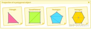
为了正确使用该技术,有必要在着色器中定义至少两个函数。为此,我们必须考虑:
用于确定曲面类型的SDF函数。
另一个计算球体投影的函数。
在Unity中,我们将创建一个类型为“Unlit shader”的新着色器,我们将其称为USB_SDF_fruit。为了理解这个概念,我们将产生一种我们称之为“切片水果”的效果。我们将把一个球体分成两部分来展示它的内部。
值得注意的是,我们将把这种效果应用于Unity中3D对象中包含的默认球体;这种球体的枢轴位于其质心,周长等于1。因此,它非常适合实现这个功能。
我们将首先在着色器中声明一个新属性,该属性将定义效果的边界。
Shader "USB/USB_SDF_fruit"
{
    Properties
    {
        _Maintex ("Texture", 2D) = "white" {}
        _Edge ("Edge", Range(-0.5, 0.5)) = 0.0
    }
    SubShader
    {
        Pass
        {
           ...
            float _Edge;
           ...
        }
    }
}
如果我们注意前面定义的_Edge属性,我们会注意到它的范围对应于-0.5f和0.5f之间的值。这是由于我们正在处理的球体的比例。
![图片[1]-《Unity着色器圣经》11.0.1 | Implementing functions with Sphere Tracing.-软件开发学习笔记](https://pic2.zhimg.com/v2-2fff28d1126463e9d5a55cfc08d80a1f_1440w.jpg)
我们将使用两个主要操作来划分球体:丢弃边缘上的像素,并在球体中心投影一个平面。丢弃像素将优化效果,并可视化我们稍后生成的平面。
我们继续声明一个SDF类型的函数来计算平面。
Pass
{
   ...
    // declare the function for the plane
    float planeSDF(float3 ray_position)
    {
        // subtract the edge to the "Y" ray position to increase
        // or decrease the plane position
        float plane = ray_position.y - _Edge;
        return plane;
    }
   ...
}
由于_Edge是从Ray的y位置减去的,因此我们的三维平面将根据属性的值在空间中以图形方式向上或向下移动。它的实现可以在本节后面看到。现在,我们将定义一些常数,这些常数将用于球体投影计算,确定平面的表面。
float planeSDF(float3 ray_position) { … }

// maximum of steps to determine the surface intersection
#define MAX_MARCHIG_STEPS 50
// maximum distance to find the surface intersection
#define MAX_DISTANCE 10.0
// surface distance
#define SURFACE_DISTANCE 0.001
#define指令允许我们声明一个可以用作全局常量的标识符。与每个宏相关联的值是根据其功能确定的,例如,MAX_DISTANCE等于场景中的十米或十个网格块。同时,MAX_MARCHING_STEPS指的是我们找到平面交点所需的步骤数。
我们继续声明一个函数来执行Sphere Casting。
float planeSDF(float3 ray_position) { … }

#define MAX_MARCHIG_STEPS 50
#define MAX_DISTANCE 10.0
#define SURFACE_DISTANCE 0.001

float sphereCasting(float3 ray_origin, float3 ray_direction)
{
    float distance_origin = 0;
    for(int i = 0; i < MAX_MARCHIG_STEPS; i++)
    {
        float3 ray_position = ray_origin + ray_direction * distance_origin;
        float distance_scene = planeSDF(ray_position);
        distance_origin += distance_scene;

        if(distance_scene < SURFACE_DISTANCE || distance_origin > MAX_MARCHIG_STEPS);
        break;
    }

    return distance_origin;
}
乍一看,上面示例中的操作看起来很难理解。然而,这并不完全复杂。首先,我们应该注意它的论点。
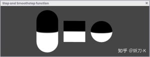
“ray_origin”向量对应于“光线的起点”,即相机在局部空间中的位置,而“ray_direction”等于“网格顶点的位置”,换句话说,等于我们正在处理的球体的位置,为什么?由于我们将根据边在基元中生成分割,因此我们需要SDF平面的位置等于3D对象的位置。
![图片[2]-《Unity着色器圣经》11.0.1 | Implementing functions with Sphere Tracing.-软件开发学习笔记](https://gamedevfan.cn/wp-content/uploads/2025/05/image-140-1024x432.jpeg)
如上所述,有必要丢弃位于平面上的球体的像素。要执行这样的评估,我们需要球体y轴上顶点的对象空间位置。使用“丢弃”语句,我们可以丢弃那些位于边缘的像素,如下面的操作所示。
if (vertexPosition.y > _Edge)
    discard;
对于这个效果,有必要在顶点输出中声明一个新的三维向量;为什么?由于其性质,像素只能在片段着色器阶段中丢弃。因此,我们必须将值从顶点着色器带到片段着色器阶段。
我们将创建一个新的向量,我们称之为“hitPos”
struct v2f
{
    float2 uv : TEXCOORD0;
    float4 vertex : SV_POSITION;
    float3 hitPos : TEXCOORD1;
};
这个矢量在我们的效果中将具有双重功能。一方面,我们将使用它来定义网格顶点的位置;另一方面,计算空间平面的位置,使两个表面位于同一点。
v2f vert (appdata v)
{
    v2f o;
    o.vertex = UnityObjectToClipPos(v.vertex);
    o.uv = TRANSFORM_TEX(v.uv, _MainTex);
    // we assign the vertex position in object - space
    o.hitPos = v.vertex;

    return o;
}
最后,我们可以丢弃位于_Edge属性上的像素。
fixed4 frag (v2f i) : SV_Target
{
    fixed4 col = tex2D(_MainTex, i.uv);

    // we discard the pixels that lie on the _Edge
    if (i.hitPos > _Edge)
        discard;

    return col;
}
如果一切顺利,我们将看到类似于图11.0.2c的效果。_Edge属性将动态修改丢弃的像素边界。
![图片[3]-《Unity着色器圣经》11.0.1 | Implementing functions with Sphere Tracing.-软件开发学习笔记](https://gamedevfan.cn/wp-content/uploads/2025/05/image-139-1024x391.jpeg)
值得注意的是,我们的效果是“不透明的”,也就是说,它没有透明度。
那些被丢弃的像素将不会被执行;因此,程序不会将它们发送到输出颜色。
如图11.0.2b所示,光线的原点由摄影机的位置给定,而光线的方向可以通过遵循同一空间中顶点的位置来计算。
这些变量的声明可以在片段着色器阶段使用_WorldSpaceCameraPos变量快速完成,然后将顶点传递给函数,如以下示例所示:
fixed4 frag (v2f i) : SV_Target
{
    fixed4 col = tex2D(_MainTex, i.uv);

    // transform the camera to local - space
    float3 ray_origin = mul(unity_WorldToObject, float4(_WorldSpaceCameraPos, 1));

    // calculate the ray direction
    float3 ray_direction = normalize(i.hitPos - ray_origin);

    // use the values in the ray casting function
    float t = sphereCasting(ray_origin, ray_direction);

    // calculate the point position in space
    float3 p = ray_origin + ray_direction * t;

    if (i.hitPos > _Edge)
        discard;

    return col;
}
在前面的例子中,我们将平面与相机的距离存储在“t”变量中,然后将每个平面的点存储在变量“p”中
有必要将我们的SDF平面投影到球体的正面。因此,我们将不得不从“SubShader”禁用“Culling”。
SubShader
{
   ...
    // show both faces of the sphere
    Cull off
   ...
    Pass
    {
       ...
    }
}
我们可以将球体的像素投影在其背面,对于平面,可以使用SV_isFrontFace语义将其投影在正面。
fixed4 frag (v2f i, bool face : SV_isFrontFace) : SV_Target
{
    fixed4 col = tex2D(_MainTex, i.uv);

    float3 ray_origin = mul(unity_WorldToObject, float4(_WorldSpaceCameraPos, 1));

    float3 ray_direction = normalize(i.hitPos - ray_origin);

    float t = sphereCasting(ray_origin, ray_direction);

    float3 p = ray_origin + ray_direction * t;

    if (i.hitPos > _Edge)
        discard;

    return face? col : float4(p, 1);
}
如果我们返回到场景,我们可以使用_Edge属性确定SDF平面y轴上的位置,如图11.0.2d所示。
![图片[4]-《Unity着色器圣经》11.0.1 | Implementing functions with Sphere Tracing.-软件开发学习笔记](https://gamedevfan.cn/wp-content/uploads/2025/05/image-138-1024x387.jpeg)
原文对照
It will be necessary to define at least two functions in our shader for the correct operation of this technique. For this, we will have to consider:
- An SDF function to determine the type of surface.
- Another function to calculate the sphere casting.
In Unity, we will create a new shader of type “Unlit Shader,” which we will call USB_SDF_fruit. To understand the concept, we will develop an effect that we will call “sliced-fruit.” We will divide a sphere into two parts to show its inside.
Noteworthy that we will apply this effect on a primitive sphere, ideally the one included in the 3D objects in Unity; why? Such a sphere has its pivot at the center of its mass and has a circumference equal to one. Therefore, it fits perfectly inside a grid block in our scene.
We will start by declaring a new property in our shader, which will define the effect’s border or division.
Shader "USB/USB_SDF_fruit"
{
    Properties
    {
        _Maintex ("Texture", 2D) = "white" {}
        _Edge ("Edge", Range(-0.5, 0.5)) = 0.0
    }
    SubShader
    {
        Pass
        {
           ...
            float _Edge;
           ...
        }
    }
}
If we pay attention to the _Edge property defined previously, we will notice that its range corresponds to a value between -0.5f and 0.5f. It is due to the volume or scale of the sphere we are working with.
![图片[5]-《Unity着色器圣经》11.0.1 | Implementing functions with Sphere Tracing.-软件开发学习笔记](https://gamedevfan.cn/wp-content/uploads/2025/05/image-141-1024x392.jpeg)
We will use two primary operations to divide the sphere: discard the pixels on the _Edge and project a plane in the sphere’s center. Discarding the pixels will optimize the effect and visualize the plane that we will generate later.
We continue by declaring a function of type SDF for calculating the plane.
Pass
{
   ...
    // declare the function for the plane
    float planeSDF(float3 ray_position)
    {
        // subtract the edge to the "Y" ray position to increase
        // or decrease the plane position
        float plane = ray_position.y - _Edge;
        return plane;
    }
   ...
}
Since the _Edge is subtracting from Ray’s y-position, our three-dimensional plane will graphically move up or down in space according to the property’s value. Its implementation can be seen later in this section. For now, we will define some constants that we will use in the sphere casting calculation, determining the plane’s surface.
float planeSDF(float3 ray_position) { … }

// maximum of steps to determine the surface intersection
#define MAX_MARCHIG_STEPS 50
// maximum distance to find the surface intersection
#define MAX_DISTANCE 10.0
// surface distance
#define SURFACE_DISTANCE 0.001
The #define directive allows us to declare an identifier we can use as a global constant. The values associated with each macro have been determined according to their functionality, e.g., MAX_DISTANCE is equal to ten meters or ten grid blocks in the scene. At the same time, MAX_MARCHING_STEPS refers to the number of steps we will need to find the plane’s intersection.
We continue by declaring a function to perform Sphere Casting.
float planeSDF(float3 ray_position) { … }

#define MAX_MARCHIG_STEPS 50
#define MAX_DISTANCE 10.0
#define SURFACE_DISTANCE 0.001

float sphereCasting(float3 ray_origin, float3 ray_direction)
{
    float distance_origin = 0;
    for(int i = 0; i < MAX_MARCHIG_STEPS; i++)
    {
        float3 ray_position = ray_origin + ray_direction * distance_origin;
        float distance_scene = planeSDF(ray_position);
        distance_origin += distance_scene;

        if(distance_scene < SURFACE_DISTANCE || distance_origin > MAX_MARCHIG_STEPS);
        break;
    }

    return distance_origin;
}
At first glance, the operation in the above example looks challenging to understand. However, it is not entirely complex. Initially, we should pay attention to its arguments.
The “ray_origin” vector corresponds to “the ray’s starting point,” e. i., the camera’s position in local-space, while “ray_direction” is equal to “mesh vertices’ position,” in other words, to the position of the sphere we are working with, why? Since we will generate a division in the primitive according to an edge, we will need the position of the SDF plane to be equal to the position of the 3D object.
As mentioned above, it will be necessary to discard the pixels of the sphere that lie on the plane. To perform such an evaluation, we will need the object-space position of the vertices on the y-axis of the sphere. Using the “discard” statement, we can discard those pixels that lie on edge, as shown in the following operation.
if (vertexPosition.y > _Edge)
    discard;
For the exercise, it will be necessary to declare a new three-dimensional vector in the vertex output; why? Because of their nature, pixels can only be discarded in the fragment shader stage. Therefore, we will have to take the values from the vertex shader to the fragment shader stage.
We will create a new vector which we will call “hitPos.”
struct v2f
{
    float2 uv : TEXCOORD0;
    float4 vertex : SV_POSITION;
    float3 hitPos : TEXCOORD1;
};
This vector will have a double functionality in our effect. On the one hand, we will use it to define the position of the mesh vertices; and, on the other hand, to calculate the spatial plane’s position so that both surfaces are located at the same point.
v2f vert (appdata v)
{
    v2f o;
    o.vertex = UnityObjectToClipPos(v.vertex);
    o.uv = TRANSFORM_TEX(v.uv, _MainTex);
    // we assign the vertex position in object - space
    o.hitPos = v.vertex;

    return o;
}
Finally, we can discard pixels that lie on the _Edge property.
fixed4 frag (v2f i) : SV_Target
{
    fixed4 col = tex2D(_MainTex, i.uv);

    // we discard the pixels that lie on the _Edge
    if (i.hitPos > _Edge)
        discard;

    return col;
}
If everything has gone well in Unity, we will appreciate a behavior similar to that of figure 11.0.2c. The _Edge property will dynamically modify the discarded pixel border.
Noteworthy that our effect is “opaque,” that is, it has no transparency.
Those discarded pixels will not be executed; therefore, the program will not send them to the output color.
As we can see in Figure 11.0.2b, the ray’s origin is given by the camera’s position, while the ray’s direction can be calculated by following the position of the vertices in the same space.
The declaration of these variables can be quickly done in the fragment shader stage using the _WorldSpaceCameraPos variable, and then passing the vertices to the function as shown in the following example:
fixed4 frag (v2f i) : SV_Target
{
    fixed4 col = tex2D(_MainTex, i.uv);

    // transform the camera to local - space
    float3 ray_origin = mul(unity_WorldToObject, float4(_WorldSpaceCameraPos, 1));

    // calculate the ray direction
    float3 ray_direction = normalize(i.hitPos - ray_origin);

    // use the values in the ray casting function
    float t = sphereCasting(ray_origin, ray_direction);

    // calculate the point position in space
    float3 p = ray_origin + ray_direction * t;

    if (i.hitPos > _Edge)
        discard;

    return col;
}
Looking at the previous example, we have stored the plane’s distance concerning the camera in the “t” variable and then stored each plane’s point in the variable “p.”
It will be necessary to project our SDF plane onto the front face of the sphere. Consequently, we will have to disable Culling from the SubShader.
SubShader
{
   ...
    // show both faces of the sphere
    Cull off
   ...
    Pass
    {
       ...
    }
}
We can project the pixels of the sphere on its back face, and for the plane, it can be projected on the front face using the SV_isFrontFace semantic.
fixed4 frag (v2f i, bool face : SV_isFrontFace) : SV_Target
{
    fixed4 col = tex2D(_MainTex, i.uv);

    float3 ray_origin = mul(unity_WorldToObject, float4(_WorldSpaceCameraPos, 1));

    float3 ray_direction = normalize(i.hitPos - ray_origin);

    float t = sphereCasting(ray_origin, ray_direction);

    float3 p = ray_origin + ray_direction * t;

    if (i.hitPos > _Edge)
        discard;

    return face? col : float4(p, 1);
}
If we return to the scene, we can determine the position on the y-axis of the SDF plane using the _Edge property, as shown in Figure 11.0.2d.
![[udemy]在 Unity 中创建 RPG 游戏的终极指南-软件开发学习笔记](https://gamedevfan.cn/wp-content/uploads/2025/04/TheUltimateGuidetoCreatinganRPGGameinUnity.webp)
![[udemy]学习在 Unity 和 C# 中创建吸血鬼幸存者风格的游戏-软件开发学习笔记](https://gamedevfan.cn/wp-content/uploads/2025/04/LearnToCreateAVampireSurvivorsStyleGameinUnityC.webp)
![[udemy] 在 Godot 4 中创建完整的 2D 幸存者风格游戏-软件开发学习笔记](https://gamedevfan.cn/wp-content/uploads/2025/05/CreateaComplete2DSurvivorsStyleGameinGodot4.webp)
![[gamedev tv] RPG核心战斗力的创造者 :学习中级 Unity C# 编码-软件开发学习笔记](https://gamedevfan.cn/wp-content/uploads/2025/04/RPGCoreCombatCreatorLearnIntermediateUnityCCoding.png)
![[gamedev tv] 完成 Godot 3D:使用 Godot 4 开发您自己的 3D 游戏-软件开发学习笔记](https://gamedevfan.cn/wp-content/uploads/2025/05/CompleteGodot3DDevelopYourOwn3DGamesUsingGodot4.webp)


暂无评论内容