目录索引

译文
继续使用USB_SDF_fruit着色器,这一次,我们将在之前生成的SDF平面上投影纹理。我们将首先添加一些稍后将使用的属性。
Shader "USB/USB_SDF_fruit"
{
Properties
{
_Maintex ("Texture", 2D) = "white" {}
// plane texture
_PlaneTex ("Plane Texture", 2D) = "white" {}
// edge color projection
_CircleCol ("Circle Color", Color) = (1, 1, 1, 1)
// edge radius projection
_CircleRad ("Circle Radius", Range(0.0, 0.5)) = 0.45
_Edge ("Edge", Range(-0.5, 0.5)) = 0.0
}
SubShader
{
Pass
{
...
sampler2D _MainTex;
sampler2D _PlaneTex;
float4 _MainTex_ST;
float4 _CircleCol;
float _CircleRad;
float _Edge;
...
}
}
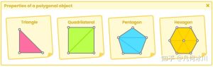
}对于这种情况,如果我们想在SDF平面上投影纹理,我们必须考虑SDF平面背面的位置和方向;为什么?请记住,平面指向正y轴。因此,纹理的方向应该相反。
![图片[1]-《Unity着色器圣经》11.0.2 | Projecting a texture.-软件开发学习笔记](https://gamedevfan.cn/wp-content/uploads/2025/05/image-147-1024x393.jpeg)
为此,我们可以使用点“p.xz”计算最大球体投射区域内的UV坐标
fixed4 frag (v2f i, bool face : SV_isFrontFace) : SV_Target
{
   ...
    float t = sphereCasting(ray_origin, ray_direction);

    if(t < MAX_DISTANCE)
    {
        float3 p = ray_origin + ray_direction * t;
        float2 uv_p = p.xz;
    }

    if (i.hitPos > _Edge)
        discard;

    return face? col : float4(p, 1);
}
现在,我们可以在tex2D函数中使用这些坐标,与整本书中使用的方法相同。
fixed4 frag (v2f i, bool face : SV_isFrontFace) : SV_Target
{
...
float t = sphereCasting(ray_origin, ray_direction);
float4 planeCol = 0;
if(t < MAX_DISTANCE)
{
float3 p = ray_origin + ray_direction * t;
float2 uv_p = p.xz;
planeCol = tex2D(_PlaneTex, uv_p);
}
if (i.hitPos > _Edge)
discard;
return face? col : planeCol;
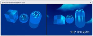
}在上一次演习中,已经被声明了一个名为“planeCol”的新四维矢量。在这个向量中,我们已经存储了SDF平面的纹理投影,方向在y轴上。如果一切顺利,我们会在场景中看到带有纹理的球体和平面。
![图片[2]-《Unity着色器圣经》11.0.2 | Projecting a texture.-软件开发学习笔记](https://gamedevfan.cn/wp-content/uploads/2025/05/image-146-1024x391.jpeg)
值得注意的是,坐标“uv_p”的起点位于网格的中心(0x,0y,0z);因此,有必要减去0.5f以使平面的投影居中。
...
planeCol = tex2D(_PlaneTex, uv_p - 0.5);
...
如果我们修改检查器材质中_Edge属性的值,我们可以注意到效果正在发挥作用。然而,有必要找到一种操作,使我们能够在_Edge等于“0.0f”时保持平面上投影的大小,并在“0.5f”和“-0.5f”之间的范围内减小投影的大小
然后,已经执行了以下操作,这简单地解决了问题,
(-abs(x))² + (-abs(x) – 1)²
所以,
...
if(t < MAX_DISTANCE)
{
float3 p = ray_origin + ray_direction * t;
float2 uv_p = p.xz;
float l = pow(-abs(_Edge), 2) + pow(-abs(_Edge) - 1, 2);
planeCol = tex2D(_PlaneTex, (uv_p * (1 - abs(pow(_Edge * l, 2)))) - 0.5);
}
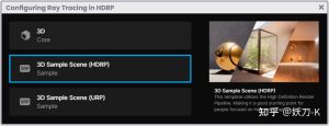
...修改_Edge属性的值后,我们将看到平面的纹理投影随着球体的体积而减小。
![图片[3]-《Unity着色器圣经》11.0.2 | Projecting a texture.-软件开发学习笔记](https://gamedevfan.cn/wp-content/uploads/2025/05/image-145-1024x393.jpeg)
我们可以通过在平面中投影一个圆来设置效果的样式,该圆遵循球体的周长。为此,我们可以执行以下操作,
...
float4 planeCol = 0;
float4 circleCol = 0;
if(t < MAX_DISTANCE)
{
float3 p = ray_origin + ray_direction * t;
float2 uv_p = p.xz;
float l = pow(-abs(_Edge), 2) + pow(-abs(_Edge) - 1, 2);
// generate a circle following the UV plane coordinates
float c = length(uv_p);
// apply the same scheme to the circle’s radius
// this way, we modify the its size
circleCol = (smoothstep(c - 0.01, c + 0.01, _CircleRad - abs(pow(_Edge * (1 * 0.5), 2))));
planeCol = tex2D(_PlaneTex, (uv_p*(1 - abs(pow(_Edge * l, 2)))) - 0.5);
// delete the texture borders
planeCol *= circleCol;
// add the circle and apply color
planeCol += (1 - circleCol) * _CircleCol;
}
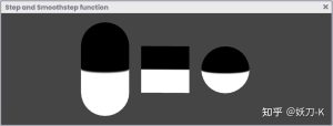
...在上一个练习中,我们根据平面的UV坐标投影生成了一个圆,并将其保存在“c”变量中。
然后,使用相同的数学方案来增加或减少圆的半径。最后,考虑到圆形只有黑色和白色,纹理投影的边缘被去除;为什么?这是由于操作结束时对这些值求和。
可以通过Inspector材质的_CircleRad特性动态修改圆半径。
![图片[4]-《Unity着色器圣经》11.0.2 | Projecting a texture.-软件开发学习笔记](https://gamedevfan.cn/wp-content/uploads/2025/05/image-144-1024x431.jpeg)
原文对照
Continuing with our USB_SDF_fruit shader, this time, we will project a texture over the SDF plane that we have previously generated. We will start by adding some properties that we will use later in effect.
Shader "USB/USB_SDF_fruit"
{
    Properties
    {
        _Maintex ("Texture", 2D) = "white" {}
        // plane texture
        _PlaneTex ("Plane Texture", 2D) = "white" {}
        // edge color projection
        _CircleCol ("Circle Color", Color) = (1, 1, 1, 1)
        // edge radius projection
        _CircleRad ("Circle Radius", Range(0.0, 0.5)) = 0.45
        _Edge ("Edge", Range(-0.5, 0.5)) = 0.0
    }
    SubShader
    {
        Pass
        {
           ...
            sampler2D _MainTex;
            sampler2D _PlaneTex;
            float4 _MainTex_ST;
            float4 _CircleCol;
            float _CircleRad;
            float _Edge;
           ...
        }
    }
}
For this case, if we want to project a texture on the SDF plane, we will have to consider the position and direction of the back face of the SDF plane; why? Remember that the plane is pointing towards the positive y-axis. Therefore, the texture should be oriented in the opposite direction.
To do this, we can calculate UV coordinates within the maximum sphere casting area, using the point “p.xz.”
fixed4 frag (v2f i, bool face : SV_isFrontFace) : SV_Target
{
   ...
    float t = sphereCasting(ray_origin, ray_direction);

    if(t < MAX_DISTANCE)
    {
        float3 p = ray_origin + ray_direction * t;
        float2 uv_p = p.xz;
    }

    if (i.hitPos > _Edge)
        discard;

    return face? col : float4(p, 1);
}
Now we can use these coordinates in the tex2D function, the same way as it has been done throughout the book.
fixed4 frag (v2f i, bool face : SV_isFrontFace) : SV_Target
{
   ...
    float t = sphereCasting(ray_origin, ray_direction);
    float4 planeCol = 0;

    if(t < MAX_DISTANCE)
    {
        float3 p = ray_origin + ray_direction * t;
        float2 uv_p = p.xz;

        planeCol = tex2D(_PlaneTex, uv_p);
    }

    if (i.hitPos > _Edge)
        discard;

    return face? col : planeCol;
}
A new four-dimensional vector called “planeCol” has been declared in the previous exercise. In this vector, we have stored the projection of the texture for the SDF plane, oriented on the y-axis. If everything went well, we would see both the sphere and the plane with textures in our scene.
Noteworthy that the starting point of the coordinate “uv_p” is at the center of the grid (0x, 0y, 0z); therefore, it will be necessary to subtract 0.5f to center the plane’s projection.
...
planeCol = tex2D(_PlaneTex, uv_p - 0.5);
...
If we modify the value of the _Edge property from the inspector material, we can notice that the effect is working. However, it will be necessary to find an operation that allows us to maintain the size of the projection on the plane when _Edge is equal to “0.0f,” and decrease its size when it is in the range between “0.5f” and “-0.5f.”
Then, the following operation has been performed, which simply solves the exercise,
(-abs(x))² + (-abs(x) – 1)²
Thus,
...
if(t < MAX_DISTANCE)
{
    float3 p = ray_origin + ray_direction * t;
    float2 uv_p = p.xz;

    float l = pow(-abs(_Edge), 2) + pow(-abs(_Edge) - 1, 2);

    planeCol = tex2D(_PlaneTex, (uv_p * (1 - abs(pow(_Edge * l, 2)))) - 0.5);
}
...
We will see the plane’s texture projection decreasing according to the sphere’s volume once we modify the _Edge property’s value.
We can stylize the effect by projecting a circle in the plane, which follows the sphere’s circumference. To do this, we can perform the following operation,
...
float4 planeCol = 0;
float4 circleCol = 0;

if(t < MAX_DISTANCE)
{
    float3 p = ray_origin + ray_direction * t;
    float2 uv_p = p.xz;

    float l = pow(-abs(_Edge), 2) + pow(-abs(_Edge) - 1, 2);
    // generate a circle following the UV plane coordinates
    float c = length(uv_p);

    // apply the same scheme to the circle’s radius
    // this way, we modify the its size
    circleCol = (smoothstep(c - 0.01, c + 0.01, _CircleRad - abs(pow(_Edge * (1 * 0.5), 2))));
    planeCol = tex2D(_PlaneTex, (uv_p*(1 - abs(pow(_Edge * l, 2)))) - 0.5);

    // delete the texture borders
    planeCol *= circleCol;

    // add the circle and apply color
    planeCol += (1 - circleCol) * _CircleCol;
}
...
In the previous exercise, we generated a circle following the plane’s UV coordinates projection and saved it in the “c” variable.
Then, the same mathematical scheme was used to increase or decrease the circle’s radius. Finally, considering that the circle has only black and white color, the edges of the texture projection have been removed; why? It is due to the sum of these values at the end of the operation.
The circle radius can be modified dynamically through the _CircleRad property from the Inspector material.
![[udemy]在 Unity 中创建 RPG 游戏的终极指南-软件开发学习笔记](https://gamedevfan.cn/wp-content/uploads/2025/04/TheUltimateGuidetoCreatinganRPGGameinUnity.webp)
![[udemy]学习在 Unity 和 C# 中创建吸血鬼幸存者风格的游戏-软件开发学习笔记](https://gamedevfan.cn/wp-content/uploads/2025/04/LearnToCreateAVampireSurvivorsStyleGameinUnityC.webp)
![[udemy] 在 Godot 4 中创建完整的 2D 幸存者风格游戏-软件开发学习笔记](https://gamedevfan.cn/wp-content/uploads/2025/05/CreateaComplete2DSurvivorsStyleGameinGodot4.webp)
![[gamedev tv] RPG核心战斗力的创造者 :学习中级 Unity C# 编码-软件开发学习笔记](https://gamedevfan.cn/wp-content/uploads/2025/04/RPGCoreCombatCreatorLearnIntermediateUnityCCoding.png)
![[gamedev tv] 完成 Godot 3D:使用 Godot 4 开发您自己的 3D 游戏-软件开发学习笔记](https://gamedevfan.cn/wp-content/uploads/2025/05/CompleteGodot3DDevelopYourOwn3DGamesUsingGodot4.webp)

暂无评论内容