目录索引
译文
矩阵(matrix)是我们在编写着色器时经常遇到的一个概念,是由一组数字组成的阵列。矩阵计算遵循一定的算术规则,经常用于计算机图形学中。
在 Unity 中,矩阵常应用于坐标空间的变换,我们可以找到以下矩阵:
- UNITY_MATRIX_MVP
- UNITY_MATRIX_MV
- UNITY_MATRIX_V
- UNITY_MATRIX_P
- UNITY_MATRIX_VP
- UNITY_MATRIX_T_MV
- UNITY_MATRIX_IT_MV
- unity_ObjectToWorld
- unity_WorldToObject
上面所提到的这些矩阵都是4*4的矩阵,意思是矩阵有四行四列,如下图所示:
![图片[1]-《Unity着色器圣经》1.1.6 | 矩阵与坐标系统-软件开发学习笔记](https://gamedevfan.cn/wp-content/uploads/2025/05/image-19-1024x327.jpeg)
我们在第1.0.2节中介绍顶点时提到在 Maya 中模型默认有两个节点,分别是 “变换”(transform)节点和 “形状”(shape)节点,它们都负责计算顶点在一个称为 “模型空间”(object-space)的空间中的位置,该空间定义了顶点相对于模型中心的位置。
模型空间中的每个顶点都要乘以一个被称为模型矩阵(UNITY_MATRIX_M)的矩阵才能得到最终坐标。通过模型矩阵,我们可以修改模型顶点的平移、旋转和缩放的值。每当我们平移、旋转或缩放我们的模型时,模型矩阵都会更新,这是怎么做到的呢?
为了理解这一概念,我们现在假设场景中有一个立方体,并希望通过模型矩阵来移动它。首先,我们选取立方体的一个顶点,该顶点位于相对于立方体中心的 XYZW [0.5f, -0.5f, -0.5f, 1] 位置。
顶点坐标中的 W 通道对应的是齐次坐标,它允许我们一并处理点和向量。在矩阵变换中,W 通道的值可以是 0 或 1 。当 W 通道的值为 1 时(例如 X,Y,Z,1),它指代的是空间中的一个点;而当 W 通道的值为 0 时(例如 X,Y,Z,0),它指代的是空间中的一个向量。在本书的后续章节中,我们将详细讨论点或向量与矩阵相乘时使用到的齐次坐标。
![图片[2]-《Unity着色器圣经》1.1.6 | 矩阵与坐标系统-软件开发学习笔记](https://gamedevfan.cn/wp-content/uploads/2025/05/image-18-1024x361.jpeg)
关于矩阵乘法有一个重要的法则,即只有在第一个矩阵的列数和第二个矩阵的行数相同时,才能进行矩阵乘法运算。我们已经知道模型矩阵是一个四行四列(4×4)的矩阵,并且顶点位置可以用一个四行一列(4×1)的矩阵表示。由于模型矩阵的列数与顶点位置的行数相等,因此可以将它们相乘,得到一个四行一列(4×1)的新矩阵,表示顶点的新位置。这一相乘的过程在着色器的顶点着色阶段进行,作用于模型中的所有顶点。
我们已经知道,模型空间指的是模型顶点相对于其中心的位置,那么世界空间、观察空间和裁剪空间又是什么意思呢?其实它们的概念是相似的。
世界空间指的是模型顶点相对于世界中心所处的位置,也就是场景的 XYZW [0, 0, 0, 1] 这一点与模型顶点位置之间的距离。如果我们想将顶点坐标从模型空间转换到世界空间,可以使用内置着色器变量 unity_ObjectToWorld。
![图片[3]-《Unity着色器圣经》1.1.6 | 矩阵与坐标系统-软件开发学习笔记](https://gamedevfan.cn/wp-content/uploads/2025/05/image-17-1024x359.jpeg)
观察空间指的是模型顶点相对于摄像机所处的位置。如果要将顶点坐标从世界空间转换到观察空间,我们可以使用内置的 UNITY_MATRIX_V 矩阵。
![图片[4]-《Unity着色器圣经》1.1.6 | 矩阵与坐标系统-软件开发学习笔记](https://gamedevfan.cn/wp-content/uploads/2025/05/image-16-1024x366.jpeg)
最后,裁剪空间(也被称为投影空间)指的是模型顶点在摄像机视锥体中的位置,它会受到摄像机的近裁平面、远裁平面和视场大小的影响。如果我们想将顶点坐标从观察空间转换到裁剪空间,可以使用内置的 UNITY_MATRIX_P 矩阵来实现。
![图片[5]-《Unity着色器圣经》1.1.6 | 矩阵与坐标系统-软件开发学习笔记](https://gamedevfan.cn/wp-content/uploads/2025/05/image-15-1024x403.jpeg)
总的来说,我们已经在概念层面上讨论了不同的坐标空间,但还没有定义变换矩阵的含义。
例如,着色器内置的 UNITY_MATRIX_MVP 指的是三个不同矩阵的乘法:M 指模型矩阵,V 指观察矩阵,P 指投影矩阵。该矩阵主要用于将物体的顶点从模型空间转换到裁剪空间。请记住,我们的模型是在三维(3D)环境中创建的,而最终投影到电脑屏幕上的对象是二维(2D)的,因此我们必须将模型从一个空间转换到另一个空间。
在本书后续的章节中学习顶点着色器时,我们会使用到着色器的 UnityObjectToClipPos 函数,届时我们将会详细回顾这些概念。
原文对照
One of the concepts that we see frequently in the creation of shaders is that of matrices. A matrix is a list of numeric elements that follow certain arithmetic rules and are frequently used in computer graphics.
In Unity the matrices represent a spatial transformation and among them, we can find:
- UNITY_MATRIX_MVP.
- UNITY_MATRIX_MV.
- UNITY_MATRIX_V.
- UNITY_MATRIX_P.
- UNITY_MATRIX_VP.
- UNITY_MATRIX_T_MV.
- UNITY_MATRIX_IT_MV.
- unity_ObjectToWorld.
- unity_WorldToObject.
All of these correspond to four by four matrices (4×4), that is, each of them has four rows and four columns of numerical values. Their conceptual representation is as follows:
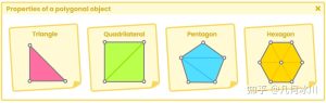
As we explained previously in section 1.0.2 where we talked about vertices, a polygon object has two nodes by default. In Maya, these nodes are known as transform and shape, and both are in charge of calculating the position of the vertices in a space called object-space, which defines the position of the vertices about the position of the object’s center.
The final value of each vertex in the object space is multiplied by a matrix known as the model matrix (UNITY_MATRIX_M), which allows us to modify the transformation, rotation and scale values of the vertices of an object. Every time that we rotate, change position or scale our object then the model matrix is updated, but how does this process happen?
To understand this we are going to suppose that we have a Cube in our scene and we want to transform its values using a model matrix. We will start by taking a vertex of our Cube that is at position XYZW [0.5f, -0.5f, -0.5f, 1] relative to its center.
It should be mentioned that channel “W” in the previous example corresponds to a “homogeneous” system of coordinates that allow us to handle vectors and points uniformly. In matrix transformations, the W coordinate can have a value of “zero or one”. When W equals one (e.g. X, Y, Z, 1), it refers to a point in space, whereas, when it equals zero (e.g. X, Y, Z, 0), it refers to a direction in space.
Later in this book, we will talk about this system when we multiply vectors by matrices and vice versa.
One of the elements to consider concerning matrices is that multiplication can only be carried out when the number of columns in the first matrix is equal to the number of rows in the second. As we already know, our model matrix has a dimension of four rows and four columns (4×4), and the vertex position has a dimension of four rows and one column (4×1). Since the number of columns in the model matrix is equal to the number of rows in the vertex position, they can be multiplied and the result will be equal to a new matrix of four rows and one column (4×1), which would define a new vertex position. This multiplication process occurs for all vertices in our object, and this process is carried out in the vertex shader stage in our shader.
We already know that object-space refers to the position of the vertices of an object concerning its center, so what do world-space, view-space, and clip-space mean? The concept is the same.
World-space refers to the position of the vertices according to the center of the world; the distance between the point XYZW [0, 0, 0, 1] of the grid in our scene and the position of a vertex in the object. If we want to transform a space coordinate from object-space to world-space, we can use the Built-in shader variable unity_ObjectToWorld.
View-Space refers to the position of a vertex of our object relative to the camera view. If we want to transform a space coordinate from world-space to view-space, we can use the UNITY_MATRIX_V matrix.
Finally, clip-space, also known as projection-space, refers to the position of a vertex of our object about the camera’s frustum, so, this factor will be affected by the camera’s near clipping plane, far clipping plane and field of view. Again, if we want to transform a space coordinate from view-space to clip-space, we can do it using the UNITY_MATRIX_P matrix.
In general, we have talked at a conceptual level about the different space coordinates, but we have not yet defined what the transformation matrices refer to.
For example, the Built-in shader variable UNITY_MATRIX_MVP refers to the multiplication of three different matrices. M refers to the model matrix, V the view matrix, and P the projection matrix. This matrix is mainly used to transform vertices of an object from object-space to clip-space. Let’s remember that our polygonal object has been created in a “threedimensional” environment while the screen of our computer, where it will be projected, is “two-dimensional”, therefore we will have to transform our object from one space to another.
Later in this book, we will review these concepts in detail when we use the UnityObjectToClipPos function included in our shader, in the vertex shader stage.
![[udemy]在 Unity 中创建 RPG 游戏的终极指南-软件开发学习笔记](https://gamedevfan.cn/wp-content/uploads/2025/04/TheUltimateGuidetoCreatinganRPGGameinUnity.webp)
![[udemy]学习在 Unity 和 C# 中创建吸血鬼幸存者风格的游戏-软件开发学习笔记](https://gamedevfan.cn/wp-content/uploads/2025/04/LearnToCreateAVampireSurvivorsStyleGameinUnityC.webp)
![[udemy] 在 Godot 4 中创建完整的 2D 幸存者风格游戏-软件开发学习笔记](https://gamedevfan.cn/wp-content/uploads/2025/05/CreateaComplete2DSurvivorsStyleGameinGodot4.webp)
![[gamedev tv] RPG核心战斗力的创造者 :学习中级 Unity C# 编码-软件开发学习笔记](https://gamedevfan.cn/wp-content/uploads/2025/04/RPGCoreCombatCreatorLearnIntermediateUnityCCoding.png)
![[gamedev tv] 完成 Godot 3D:使用 Godot 4 开发您自己的 3D 游戏-软件开发学习笔记](https://gamedevfan.cn/wp-content/uploads/2025/05/CompleteGodot3DDevelopYourOwn3DGamesUsingGodot4.webp)


暂无评论内容